Development System mikroElektronika BIGAVR6
BIGAVR6 is a development system that supports a wide range of 64- and 100-pin AVR MCUs.
Detailed Description
The BIGAVR6 development system supports a wide range of AVR MCUs. Newly released AVR microcontrollers will be supported by a new version of AVRFlash software that is updated regularly.
High-Performance On-Board USB 2.0 Programmer
On-board USB 2.0 programmer AVRprog2 doesn't use bootloader or any similar software for programming. The whole AVR memory and all pins are available to you. This is a fast USB AVR InSystem programmer ideal for your future projects. Our latest AVRprog2 Programmer is driven and powered by a single USB port on a PC. No additional AC power adapter is needed. The programmer is recognized by Windows, which simplifies the driver installation. The programmer board is specifically designed for In-Circuit Serial Programming (ICSP). The External Programmer and JTAG can be connected and used with the BIGAVR6 development system.
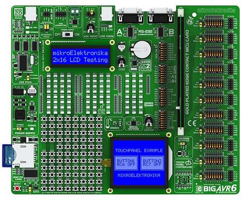
What's On-Board
- Double RS-232 communication with a PC or a microcontroller is performed via DB9 connectors.
- System can be configured by means of DIP switches. Each DIP switch configures one part of the system.
- Digital thermometer DS1820 measures temperature from -55°C to 125°C. It is connected to the system via socket.
- System supports 64- and 100-pin TQFP MCU Cards. It comes with an ATMEGA128.
- Potentiometer is used for testing multiple A/D conversions. Inputs can be configured via jumpers.
- USB or external power supply source is selected by moving a jumper. Power supply switch turns the system on/off.
- Serial EEPROM 24AA01 can store up to 1Kbit of data and uses I2C communication.
- All pins are connected to the IDC10 connectors for further expansion.
- 86 LEDs (Light Emitting Diodes) are used to indicate the logic state of all MCU pins.
- On-board jumpers are used for pull-up or pull down port configuration. They are available for all pins.
- 86 push buttons are used to excite microcontroller digital inputs. These buttons are connected to all microcontroller pins.
- DIP switch is used to separate port pins from pull-up or pull down resistors.
- Very fast, on-board USB 2.0 programmer. There is no need for connecting the external programmer.
- LCD can be connected to the board via the on-board connector that is also connected to MCU pins.
- LCD Contrast Potentiometer is used for adjusting LCD Contrast.
- Touch Screen can be connected to the board via the Touch screen connector. There is also a Touch Screen controller.
- External power supply can be DC or AC. On-board jumper is used for selecting external power supply.
- USB connector with LED indication for microcontrollers with USB facilities.
- Graphic LCD 128x64 can be easily connected to the board via the on-board connector that is linked to MCU pins.
- All pins are marked on the back of the board. These marks provide basic information on the pins.
- Voltage level to be applied when a button is pressed (GND or +5V) is selected via the on-board jumper.
- CAN module is used for communication with other microcontrollers.
- Reset circuit is used to reset the microcontroller. It is connected to the MCLR pin of the microcontroller.
- GLCD Contrast Potentiometer is used for adjusting GLCD Contrast.
- Real-Time Clock (RTC) DS1307 with a battery supply is used to keep track of the current time.
- On-board connectors are used for programming with External programmer.
- JTAG port supports in-circuit debugging and firmware programming.
- MMCSD card slot enables you to use MMCSD memory cards easily.
- Voltage reference used for A/D converter can be VCC (5V) or 4.096 V.
- On-board LCD and GLCD holders ensure proper display placement.
Examples provided with this development system will show you how to connect AVR microcontrollers with other peripheral components and how to develop your prototype device easily. Each example contains a detailed description of the relevant program including comments.
Package
- BIGAVR6 development system.
- BIGAVR6 MCU Card with ATMEGA128 Microcontroller.
- USB cable.
- CD with software, drivers and examples in C, BASIC and Pascal.
- Printed documentation that includes: BIGAVR6 Manual, BIGAVR6 Schematic Diagram, AVRprog Manual and Quick Guide for Installing USB Drivers.
Other Names:
BIGAVR6, MEBIGAVR6, BIGAVR6, ME BIGAVR6, BIGAVR6 ME-BIGAVR6, BIGAVR6 ME-BIGAVR6
