Stanford Research Systems
Function generators have been around for a long while. Over time, these instruments have accumulated a long list of features. Starting with just a few knobs for setting the amplitude and frequency of a sinusoidal output, function generators now provide wider frequency ranges, calibrated output levels, a variety of waveforms, modulation modes, computer interfaces, and in some cases, arbitrary functions. The many features added to function generators have complicated their design and increased their cost. There is an opportunity for a radical re-design of the familiar function generator using direct digital synthesis (DDS).
DDS provides remarkable frequency resolution and allows direct implementation of frequency, phase and amplitude modulation. These features which were 'tacked-on' to function generators now are handled in a clean, fundamental way by DDS.
Direct Digital Synthesis
Many of the concepts of DDS are illustrated by the way in which a sine wave is generated. The figure below shows a block diagram of a simple DDS function generator. The sine function is stored in a RAM table. The RAM's digital sine output is converted to an analog sine wave by a DAC. The steps seen at the DAC output are filtered by a low pass filter to provide a clean sine wave output.
 |
|
| Simple DDS Function Generator. |
The frequency of the sine wave depends on the rate at which addresses to the RAM table are changed. Addresses are generated by adding a constant, stored in the phase increment register (PIR), to the phase accumulator. Usually, the rate of additions is constant, and the frequency is changed by changing the number in the PIR.
The frequency resolution depends on the number of bits in the PIR. If the PIR, adder, and phase accumulator support 48-bit additions, then the fractional frequency resolution is one part in 247, or about 1×10¹⁴. That means a 48-bit DDS generator can provide better than 1 µHz resolution on a 10 MHz output. There are a few more details which need to be addressed in order to understand DDS in this application. Questions about sample rate, RAM size, DAC resolution, filter characteristics, and spectral purity of the output must be answered.
Samples per Cycle
Our intuition might suggest that a large number of samples are required for each cycle of the sine wave to achieve good spectral purity of the output. A sketch of a sine which is approximated by a small number of samples per cycle hardly looks like a sine wave. Remarkably, only about three samples are required during each cycle. In fact, if we could make an arbitrarily sharp, low-pass filter, we would need only two samples per cycle.
 |
|
| Sampled Sine Wave. |
To motivate this, consider the case where we have four samples per sine cycle. This situation is shown below. The sampled sine is reduced to a pulse train (or a square wave, if we started sampling at 45 degrees instead of at 0 degrees). The Fourier spectra of this pulse train has components at f, 2f, 3f.. etc. If we can arrange the low pass filter to eliminate the harmonic components of the pulse train, then we are left with the fundamental (a pure sine wave at frequency f).
In the more general case, generating an output at f by sampling at a rate of fs, the lowest frequency Fourier component at a frequency of fs – f. This simple result becomes the basis of the low pass filter specification: the filter should pass f but stop fs – f.
Filters
The graph below shows a low pass filter transfer function. As we have seen, the filter must pass the highest frequency which we wish to generate (fmax), but must begin its stop-band at fs–fmax. Steep rolloff filters with high stop-band attenuation are hard to build. A reasonable compromise in this trade-off occurs when fmax=fs/3. This allows the filter a one octave transition band.
 |
|
| Low pass filter for DDS outputs. |
What stopband attenuation is needed? This depends on the spurious component specification of the output. A typical specification for a function generator application would be –70 dBc.
Cauer (elliptic) filters are a good choice for this application. They have fast transition bands and may be designed with very low ripple in the pass band. The specification for this example is met by a ninth degree Cauer filter.
Bessel Filters
While Cauer filters are the best choice for CW applications, they are unusable for arbitrary waveform generation. In the time domain, Cauer filters have a very nasty overshoot. A much better choice for arbitrary waveforms (or ramps and triangles) is the Bessel filter. The Bessel filter has a slower rolloff when compared to the Cauer filter, but it is nearly phase-linear. The lack of dispersion in a phase-linear filter will preserve the pulse shape and prevent any ringing in the time domain. A seventh degree Bessel filter, with a –3 dB cutoff of fc = fs/4, is a good choice for filtering arbitrary waveforms. This filter will exhibit an output risetime of 0.35/fc.
DAC and RAM Requirements
Big, fast RAMs and high-speed, high-resolution DACs have made DDS a viable technology for function generator applications. How big, how fast, and what resolutions are required?
As we have seen, a maximum practical output frequency is fs/3. So the DDS phase accumulator, RAMs, and DACs must run at three times the maximum desired output frequency. The DAC resolution depends on the spurious component specification for the output (or the desired arbitrary waveform resolution). The DAC's quantization error and non-linearities lead to spurious outputs. To get a rough idea of the magnitude of the spurious frequency component, realize that the difference between the actual output of the DAC and the desired sine value is the source of these spurious output components. So a 12-bit DAC, which is linear and monotonic to 2 LSBs, will have output errors on the order of one part in 2048, or about –66 dB.
A short RAM table is another way to get the wrong value out of the DAC. To avoid 'phase quantization noise', there should be two more bits of address to the RAM than bits in the DAC.
Extending Frequency Range
The frequency range of the DDS output may be extended by a variety of techniques. Depending on which technique is used, some of the advantages of DDS may be lost. Just as with more conventional frequencies synthesizers, the DDS output may be doubled, mixed with other fixed sources, or used as a reference inside of a phase-locked loop.
Modulation Techniques
The power and elegance of DDS are most apparent when a modulated source is required. The frequency of the output may be changed instantly to any frequency from DC to fmax by simply changing the number in the phase increment register. Figure 4 shows the block diagram of a DDS phase accumulator with programmable modulation capabilities.
 |
|
| Figure 4. | DDS phase accumulator with modulation processor. |
This phase accumulator, which has been optimized for function generator applications, has two phase increment registers: PIRA and PIRB. A 48-bit wide multiplexer can switch between the PIRs in a single clock cycle. The modulation processor can modify the PIRs at a rate of up to 10 million bytes per second, filling one PIR while the other is used as an input to the adder.
Complex modulation programs may be stored in the modulation RAM. This RAM contains op-codes and data for operation of this processor. When programmed for a log frequency sweep, a list of up to 4000 discrete frequencies are stored in the modulation RAM by the host system. The modulation processor modifies PIRA while the adder is using PIRB and vice-versa.
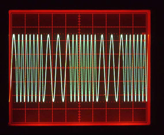
More complex modulation programs may be stored, such as frequency modulation by any arbitrary function, linear or log sweeps, frequency hopping (Figure 5), etc. Phase modulation is easily done by programming PIRA with the nominal frequency, and using PIRB, which contains the nominal phase increment plus any desired phase shift, for a single clock cycle.
 |
|
| Figure 5. | Frequency shift keying of sine wave. |
Wide frequency or phase deviations are no problem. Any phase or frequency hop may be programmed and executed in a single clock cycle. And since the PIRs may be modified very quickly, modulation frequencies up to several hundred kilohertz are possible.
In fact, arbitrary modulation programs may be stored. This feature allows the function generator to be used for modem testing, communications, bit error rate determination, etc.
Amplitude Modulation
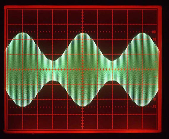
There are two approaches for amplitude modulation (Figure 6) of the output waveform. Either the digital outputs from the RAM or the analog output from the DAC may be multiplied by the desired amplitude. The later approach is better for function generators, so that either an internal or external source may be used for amplitude modulation.
 |
|
| Figure 6. | Amplitude modulation of sine by sine. |
Arbitrary Functions
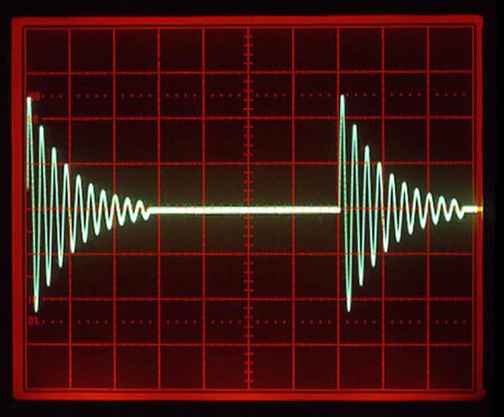
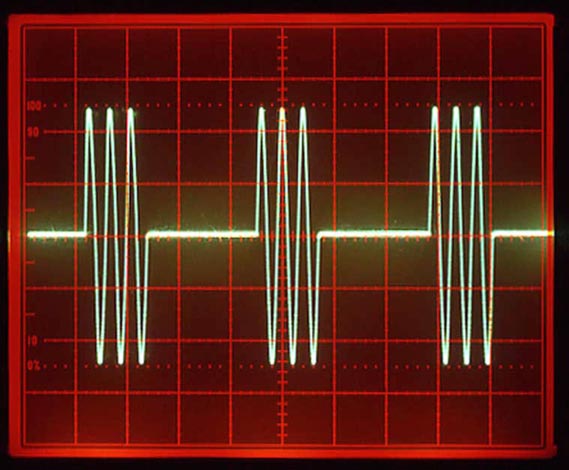
One of the immediate benefits of the DDS architecture is that arbitrary waveform generation comes along for free. Instead of storing a sine table in the waveform RAM, a list of arbitrary values is saved. The phase accumulator is programmed to step through the stored values, one at a time, to play back the desired waveform through the output DAC. The DDS's arbitrary waveform capability simplifies the task of generating the other 'standard' waveforms found in function generators (Figure 7, 8). Ramp, sawtooth, and even Gaussian white noise may be generated by changing the list of values in the waveform RAM.
 |
|
| Figure 7. | Arbitrary waveforms. |
 |
|
| Figure 8. | Three cycle burst of sine wave. |
The phase accumulator must be designed to support certain modes that are required for arbitrary waveforms. The rate at which RAM values are retrieved may be changed by simply using a different PIR value. However, variable record lengths, triggering functions, and wrap-around addressing are unique to arbitrary function generation.
As previously mentioned, a Bessel filter is required for arbitrary waveform generation. The Bessel filter will smooth the steps at the DAC output. With a –3 dB cutoff frequency, fc, of fs/4, the output will show a controlled rise time of 0.35/fc without overshoot.
Square Waves
Square waves are a special case for the DDS. One might think that a square wave could be generated by loading +1 and –1 into the waveform RAM. Indeed they can, but with the unfortunate restriction that the square wave edges must be synchronous with the DDS sample clock. This restriction would greatly limit the resolution of available frequencies: especially at high frequencies.
A much better approach for generating square waves is to generate a clean sine wave, then discriminate the sine into a square wave. In this way, square waves will have the same frequency range and resolution as sine waves.
Output Amplifiers
The output amplifier used in a DDS function generator must meet some stringent requirements. In order to preserve waveforms generated in the arbitrary mode, the amplifier must have a wide and flat pass band, and exhibit a phase linear response well past the cutoff frequency of the Bessel filter.
The amplifier's bandwidth also determines the rise time of the square wave output. Here again, a well behaved (phase linear) rolloff is required to prevent overshoot on the square wave output.
Finally, the output amplifier must be able to drive 10 Vpp into a 50 Ω load, meet distortion and settling specifications, and be protected against short circuits or connection to external power supplies. The output amplifier should exhibit a 50 Ω output impedance regardless of output level setting.
To generate low signal levels, most function generators have output attenuators. The attenuators allow the output amplifier to work within a limited range of output levels so that distortion and signal-to-noise ratios remain constant as the output levels are changed.
Floating Generator
Many applications require that the function generators be able to provide a signal to a load which is not ground referenced. Even if the load is nominally ground referenced, a floating generator output will provide a much cleaner signal because system ground loops are eliminated. It is important that the generator output shield is floating under all circumstances – even when the function generator is connected to a GPIB controller, or if an external frequency reference is connected to the instrument.
ASICs
DDS provides a new, clean, design approach for function generators. Much of the analog 'baggage' required for function generators is handled by digital logic circuits. Unfortunately, these logic circuits are big, complicated and have to run fast. For example, a 15 MHz DDS requires a 48-bit adder operating at 40 MHz with lots of glue logic. Fortunately, application specific integrated circuits (ASICs) provide a low cost solution to the problem.
A TTL prototype of the phase accumulator diagrammed earlier required about 150 ICs. The prototype was just able to work with a clock of 10 MHz. ACMOS gate array of the same design was fabricated in a 68-pin PLCC plastic package. The gate array operates at 40 MHz (worst case), uses about 0.25 watts of power, and has a recurring cost of about $10.
Conclusions
DDS based function generators are just beginning to appear in the market. These function generators offer substantial performance improvements, at reduced costs, over conventional analog function generators. As the cost of ASICs, RAMs and DACs decline, while their speed and resolution increase, expect to see DDS based function generators soon replace their analog counterparts.
