Lee H. Goldberg, Electronic Products
Doesn’t it sometimes seem as though smartphones, tablets, and other mobile devices know precisely when you have moved beyond the reach of a convenient wall plug, choosing precisely that moment to run out of juice? Too often my recent experience with a slick new Android smartphone, which quickly became an indispensable part of my professional and personal life, was to find myself with a near-dead battery halfway through a busy day. Rather than go back to my old flip phone, I decided to solve the problem using a decidedly green solution in the form of a solarized mobile USB recharging station. The goal became to build a compact power pack that fits neatly in the bottom of the little utility bag I always carry around that contains a regulated USB power supply and a hefty battery pack with enough capacity to charge several smartphones or a mid-sized tablet. To ensure maximum flexibility, I wanted the battery’s charging circuit to be able to pull its juice from any available USB port or a small PV array.
Component selection
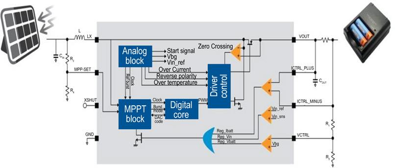
For simplicity’s sake, I decided to base the power pack on one of the new crop of single-chip maximum power point tracking (MPPT) solar charge controllers, such as STMicroelectronics’ SPV1040 and Texas Instruments’ BQ24650. In the end, I decided on ST’s SPV1040 because of the flexibility it offers in terms of input voltage (0.3 to 5.5 V) and its high levels of integration and efficiency (Figure 1). The part integrates a high-efficiency, PWM-based step-up converter with a MPPT controller that optimizes its input impedance to match the solar panel’s characteristics, which vary according to how much solar input it is receiving. Besides being able to extract the most power from whatever solar panel I find for the project, a charger based on the SPV1040 can be easily adapted to accept power inputs from an alternate USB source. It also has protection circuits that disable the PWM converter if either a selectable current threshold (up to 1.8 A) is reached or a programmed temperature limit (up to155°C) is exceeded.
 |
|
| Figure 1: |
STMicroelectronics’ SPV1040 is a low-power, low-voltage, monolithic step-up converter with an input voltage range from 0.3 to 5.5 V, which includes electrical and thermal protection, as well as MMPT tracking circuitry to maximize the energy produced by even a single solar cell. (Courtesy of STMicroelectronics.) |
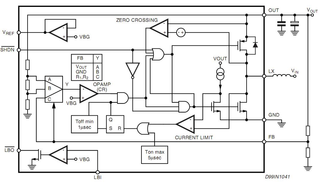
In order to power my smartphone or other USB devices from the battery pack, I used ST’s L6920 voltage boost controller (Figures 2 and especially 2a) to regulate the pack’s output up to the 5 V a USB device expects to see. Its wide input voltage range (0.6 to 5.5 V) gave me lots of flexibility in how I configured the battery pack.
 |
|
| a) | |
 |
|
| b) | |
| Figure 2: |
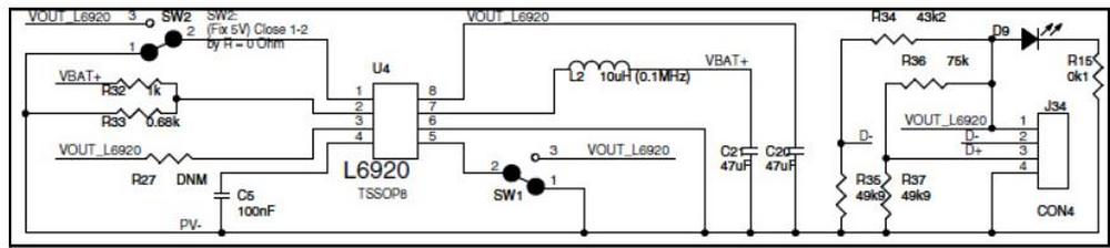
STMicro’s L6920 high-efficiency step-up converter (a). As shown in a schematic (b), the L6920 regulator (U4) provides regulated 5-V power to an external device via the standard USB connector (J34) found on any laptop or USB hub. (Courtesy of STMicroelectronics.) |
At first, I was tempted to use lithium-based batteries (Li-ion or LiPo) because they offer higher energy densities and faster charging, but began to have second thoughts after a friend reminded me of their less-than-ideal thermal characteristics, which could be aggravated by even a slight overcurrent condition during either charge or discharge. After remembering the recent stories about laptop fires, I realized that putting a potentially cranky battery pack at the bottom of my thick bag where it would have a tough time dumping any heat it generated might be a very bad idea. Although nickel metal hydride (NiMH) batteries do not pack the punch of lithium cells, they are safer, more readily available, and can cheerfully work with a relatively simple charging circuit.
For the prototype, I took the minimalist route and built a pack of four AA cells. Since I was looking for maximum capacity, I chose the Energizer NH15, which has a nominal 1.2 V output voltage and a rated capacity of 2,300 mAh. This is not the humongous capacity I had originally hoped for, but it was easy to build and more than sufficient to put a full charge on my smartphone, making it a good compromise for the first pass of the prototype. I suspect that for the next revision I will use a set of NiMH D cells, which are available with capacities of 6,000 to 8,000 Ah.
Construction
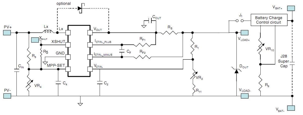
While researching app notes, I discovered that STMicro already had a nice reference design for a small MPPT charger capable of charging either NiCd or NiMH batteries from a solar panel with an output of up to 5 W. The reference design even includes a small PV cell (320 mW) and an on-board supercap for demonstrating an energy-harvesting application. I broke the connection to the supercap and connected it to the battery pack I built, and am in the process of adjusting some of the on-board resistor values to accommodate the different load. Fortunately, the application note (STMicro document # AN3319) provides clear instructions on calculating the approximate values and fine-tuning them from there. I expect I will do the same when I choose the larger solar array, which will go into the final design.
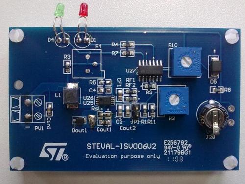
Although it needs a bit of additional circuitry to provide a USB power output and charge the battery from a USB source, this design provides a solid, easy-to-implement foundation for my power system. With a bit more money than time, I purchased an eval board (STMicro’s ISV006V2, Figure 3, 4), available from the Digi-Key on-line catalog.
 |
|
| Figure 3: |
STEVAL-ISV006V2 Evaluation board from STMicroelectronics. |
 |
|
| Figure 3: |
STMicroelectronics’ ISV006V2 evaluation board is a complete solar battery charger based on the SPV1040 which can charge either NiCd or NiMH batteries. (Courtesy of STMicroelectronics.) |
Adding the L6920 regulator to provide a 5 V USB supply was pretty straightforward (again, refer to Figure 2b), but adding the capability to charge off of a USB port has proven to be a little trickier. I had intended to use the SPV1040 to also charge the battery pack from a USB 5 V supply, but ran into a bit of trouble figuring out how to keep its impedance-matching circuitry, from either overdrawing the output or interacting in some other unhelpful way. I have a call in to the STMicro application engineering group and expect an answer shortly, but, for the moment, my unit is a solar-only system. Should there be no simple way to reuse the SPV1040’s capabilities, I will incorporate a standalone USB charger based on a device like ST’s L6902.
A work in progress
At this point, I am still cobbling the L6920 regulator/charger into the eval board, but it is already feeding my makeshift battery pack (I am waiting for the battery holder for the AA cells to arrive) from the small solar array quite nicely. The adjustments for the current and voltage sensing that control the charger will require a bit more tweaking for best results, but that will have to wait until I get a higher-powered input from either the L6920 or a larger PV array. I am looking at a few high-efficiency panels that are small enough to fit within the 6 x 7 in. confines of my gadget bag, but still big enough to generate a meaningful amount of power (1 to 2 W), as well as a larger 5 W array that I can carry in my computer bag. However, before I look into that much further, I will contact ST’s apps engineer to see if I can get the SPV1040 to charge the batteries off of a 5 V USB input. Once that’s done, you will not catch me at trade shows with that far-away “where’s the darned wall outlet” look on my face.
