Diotec Semiconductor
 Standard LEDs are widely used for all kind of lighting purposes such as optical indicators and signal lights, marking lights, display backlights, interior and furniture lighting and much more. New approaches even use standard LED arrays to replace fluorescent lights (“neon tubes”). Standard LEDs are robust, long-living and available in high volumes at low costs; their power consumption is on a very low level below 100 mW. The driving current of such devices is typically 20 mA 1), resulting in a forward voltage drop between 2 and 4 V. The following describes a cost effective solution to drive such LEDs by means of the Current Limiting Diodes CLxxMyy series offered by Diotec. They are available with 15, 20 or 40 mA and maximum 90 V: CL15M35, CL20M35 and CL40M35 in SMA package, and CL15M45, CL20M45 and CL40M45 in SMB.
Current Limiting Diodes (CLD)
Like a Zener diode keeps a voltage constant over a wide range of Zener current, the Current Limiting Diode or CLD keeps a current constant over a wide range of forward voltage. Figure 1 shows the typical IF vs VF curve of such CLD device, including the symbol and current/voltage definitions. When applying a positive voltage from anode to the cathode (indicated by cathode mark), the current rises until it reaches a constant value IP. The start of this current limiting area is defined by the limiting voltage VL, above which IL = 80% of IP is reached. IP remains constant, unless a maximum admissible voltage VAK is reached, above which a breakdown happens and the device can be destroyed. In reverse direction, the voltage VR is quite quickly reached. So operating voltage range is between VL and VAK, where current is kept to a constant value IP; the reverse direction is normally not used.
 |
| Figure 1. |
Taking the function of the CLD into account, such device can be used to drive LEDs with a constant current IP from a variable voltage source VIN, see Figure 2. The only condition is to limit the voltage across the CLD to a value less than VAK; that voltage is the difference between VIN and the voltage drop at the LED, VF-LED.
 |
| Figure 2. |
The CL20Mxx is designed for an IP of 20 mA, which is the typical driving current for Standard LEDs; the VAK is 90 V. So in the easiest case, this CLD can be used to drive a single LED from a voltage source ranging from about 10 VDC up to 90 VDC. For higher driving currents, the CL40Mxx offers an IP of 40 mA. CLDs can be even operated in parallel; of course then the power dissipation / power losses will increase as well.
However, in most cases there is an AC voltage source, so additionally a (bridge) rectifier device is required. If the circuit is connected directly to the 110 V/230 VAC mains, VIN can reach quite high levels up to 350 V peak. So existing designs require a lot of additional devices, in order to reduce the incoming voltage to an acceptable level; they further require electrolytic capacitors to keep that voltage constant. As a result, such circuits are complex and expensive, and their lifetime is limited mainly by the electrolytic capacitors used.
The following describes how by means of just a bridge rectifier, one or two CLDs, either an array of LEDs or an AC capacitor, a circuit for direct operation at 110 VAC or 230 VAC mains can be build.
Solution up to now: requiring 5 components, having limited lifetime
Figure 3 shows how up to now LEDs are driven at AC mains. The Zener diode, electrolytic capacitor and power resistor is required to keep the forward current IF through the LED constant. The electrolytic capacitor has got the shortest lifetime of all components in the circuit and is the limiting element. During turn-on, a current peak can occur at the bridge, caused during initial charge of the AC and electrolytic capacitor. Therefore here the S250 by Diotec is used, featuring a very high forward surge rating of 40 A (at 50 Hz).
 |
| Figure 3. |
New Solution, Example 1:
only 3 components and improved lifetime 2)
 |
| Figure 4. |
The circuit on Figure 4 simply needs 3 components to drive one (or more) Standard LEDs at a wide input range. The AC capacitor C has got a certain dynamic impedance
![]()
Depending on the output power (and related to that, the input or mains current), there is a voltage drop across this impedance. C has to be chosen such way that the voltage drop is big enough to ensure that VAK of the CLD is not exceeded.
New Solution, Example 2:
only 3 components for driving LED arrays at 110 VAC2)
 |
| Figure 5. |
Here (Figure 5) not only one, but an array of Standard LEDs is used. The resulting voltage drop across the series of LEDs is big enough to ensure VAK is not exceeded. Thus, by only one rectifier bridge and one single CLD a complete LED luminaire, operated at 110 VAC, can be done. The here used Protectifiers® bridge S125K has the advantage of an increased ESD capability, and provides as such additional protection for the LED array.
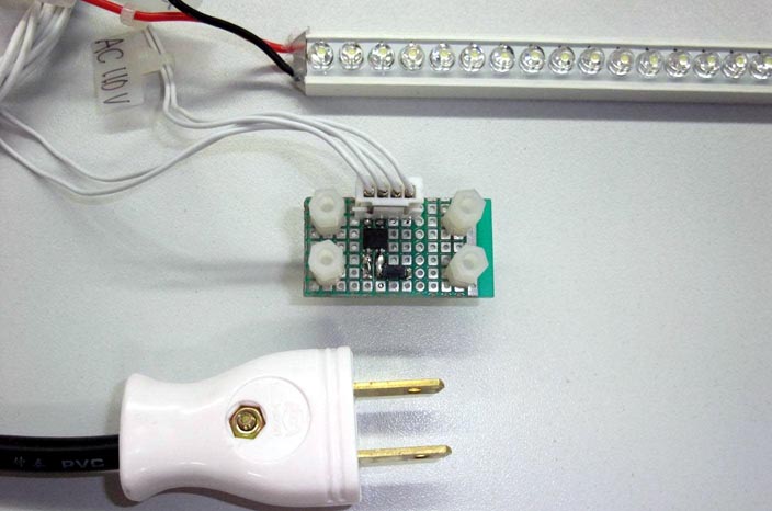 |
| LED array driven at 110 VAC by a bridge rectifier and a CLD. |
New Solution, Example 3:
only 3 components for driving LED arrays at 230 VAC 2)
Here (Figure 6) the same circuit, but operated at 230 VAC mains. Due to the higher peak voltage, more LEDs have to be connected in series. Anyway, a single rectifier bridge is enough to complete the whole circuit! The here used Protectifiers® bridge S250K has the advantage of an increased ESD capability, and provides as such additional protection for the LED array.
 |
| Figure 6. |
An additional mains fuse is recommended to provide circuit protection in case of any unforeseen shorts 2).
1 One should not mix up Standard LEDs with Power LEDs, where driving current is in the range of 350 to 700 mA (thereabout refer to the Application Note “Diotec Products for Power LED Drivers”)
2 This design idea describes an application proposal and shall not considered as assured and proven characteristic of a circuit. No warranty or guarantee, expressed or implied is made regarding the capacity, performance or suitability of any circuit etc, neither does it convey any license under its patent rights of others.
