EEWeb Pulse
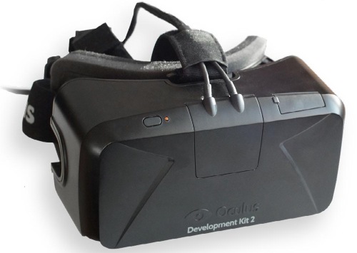
It’s the virtual reality headset that is making waves in the industry. The immense hype for the Oculus Rift began when a prototype of the headset debuted on Kickstarter back in 2012 in development kit form. In 2014, the company released the updated DK2 platform for users to start developing virtual reality games and apps before the headset became available for commercial release. The Oculus Rift boasts unprecedented low-latency visuals and stereoscopic 3D screens that offer the most immersive virtual reality experience to date. So what’s behind the success of the Rift? In today’s TechXposed Teardown, we will take a look at what makes this virtual reality headset work so effectively.
To see what makes this virtual reality headset work, you will need to remove the USB and HDMI cables, which provide power and video to the headset.
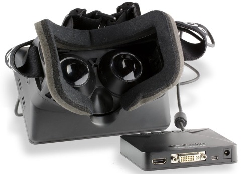
Inside the headset, a set of lenses can be twisted out, and then you’ll need to remove the four screws holding the headset together. Four more screws are under plugs that can be pried out.
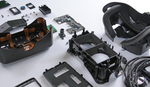
Separate the plastic shell to reveal the electronics and disconnect the flex circuit holding the two pieces together. You can see the flex circuit covers nearly the entire outer shell. The flex circuit powers 40 infrared LEDs used by the positioning tracking camera.
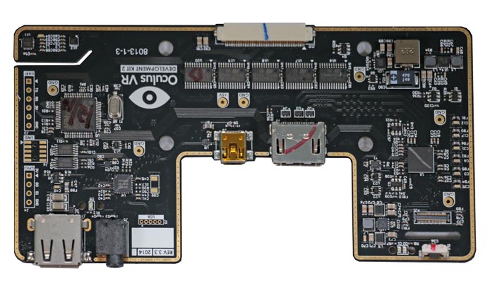
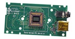
The logic board is held in place by three screws and a flex circuit threaded through it that connects to the display. The HDMI signal is passed through a Toshiba HDMI interface bridge and then to the display. Five STMicroelectronics low-voltage constant c urrent LED sink drivers drive the 40 IR LEDs. An STM32L100 ARM Cortex-M3 and a Cypress USB 2.0 hub controller round out the logic board. Other than the Oculus logo, there’s not much to see on the back.
 |
|||||
| Logic Board | |||||
|
|
||||
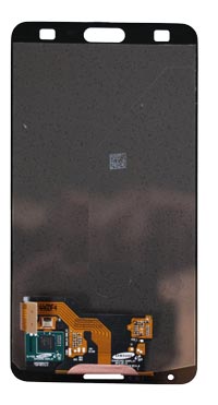
Removing a few more screws frees the display from its housing and exposes a few Samsung logos and a Synaptics touch controller. After peeling off the rubber enclosure, we find a complete Samsung screen from the Galaxy Note 3, a 5.7-inch full HD super AMOLED capacitive touchscreen.
Finally, to get inside the positional tracker, pull off the stand, pry off the faceplate, twist off the IR lens filter, and remove some screws. Inside, you’ll find the imager, lens, and an LED board.
