The other day Linda from Purchasing came to me with a problem: Lou from Operations needed to source a replacement for a shorted diode on a switching power supply. The darned thing was marked with a strange part number that no amount of Googling could decipher.
There was a recognizable logo marking, but that manufacturer could not provide a data sheet. The part number was from a previously acquired company and was unique to a specific customer. We were on our own.
Fortunately there was a second identical unit in for repair, and Lou was able to provide me with a good diode of the same type. Now all I had to do was figure out what it was. A standard rectifier diode? A zener? Schottky? Reverse voltage breakdown rating? Junction capacitance? Recovery time?
From the DO-41 package size it was easy to deduce that the rating was a watt. It was also easy to inject various currents and measure the forward voltage drop to determine that it was not a Schottky diode. Hooking up a few power supplies in series and gradually increasing the reverse voltage (with adequate series current limiting resistance in case a zener threshold was reached) proved it was not a zener diode – at least not below 200 volts.
The required PIV rating could be resolved by initially substituting a test diode with a high voltage rating, and scoping later.
This left only the unknown junction capacitance, Cj, and reverse recovery time, Trr. This is the time that a diode remains conducting when suddenly switched from forward to reverse biased. I had to figure out a way to measure these parameters. Not with exotic equipment; just enough to get in the ballpark – in other words, a function generator with a falltime of 40 ns, and a 100 MHz scope, which was all I had to work with.
The test setup was easy: Drive the diode-under-test (DUT) with a 5 V pulse – DC offset set mostly negative to bias the diode on only during positive peaks. Scope both sides of the DUT and trigger on the turn-off edge. Varying the DC voltage offset controls the DUT forward voltage and conduction current. Measure the DUT conduction current as the voltage dropped across its series 50 Ω resistor.
The first thing to do was to characterize the test setup. How does a Mickey Mouse® test like this relate to real diodes? That was determined by first measuring some known DUTs for comparison and determining the validity of the setup. I tested the following DUTs and found the results quite interesting:
- 1N4002 – standard everyday rectifier with specified CJ of 15 pF and unspecified Trr
- 1N4148 – high-speed switching diode with specified CJ of 4 pF and Trr of 8 ns
- MUR880 – high current, fast recovery rectifier diode with specified CJ of 300 pF and Trr of 200 ns
- The mystery DUT
The time scale of 100 ns/div is constant for all images for ease of comparison.
 |
|
| Starting with a 1N4002, the pulse generator's DC offset was set so that the high of the pulse is at zero volts, two divisions from the top, falling to –5 V reverse bias. The DUT has not gone into conduction, and the very slight negative current (blue trace) is due to the DUT's small CJ capacitance. |
|
 |
|
| For future reference, a 120 pF capacitor was temporarily added across the DUT, then removed for the remaining measurements. The blue current was due only to the capacitance and must be distinguished from reverse current. |
|
 |
|
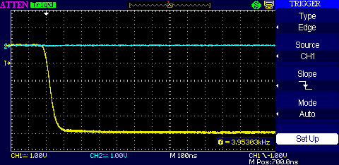
| The pulse generator DC offset was set 400 mV more positive to just begin turning the DUT on. The high yellow portion at left just before the falling edge shows the 400 mV forward voltage across the DUT. The large voltage step results in a small reverse current flowing. |
|
 |
|
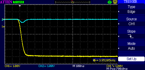
| The DC offset raised 100 mV to turn the DUT on harder, VF = 500 mV. Reverse current of 2 V/50 Ω = 40 mA, lasts for about 100 ns. |
|
 |
|
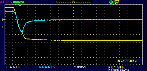
| The DC offset is raised another 100 mV to turn the DUT on even harder, VF = 600 mV. Now the reverse current reaches 60 mA and the recovery time has become very noticeable. |
|
 |
|
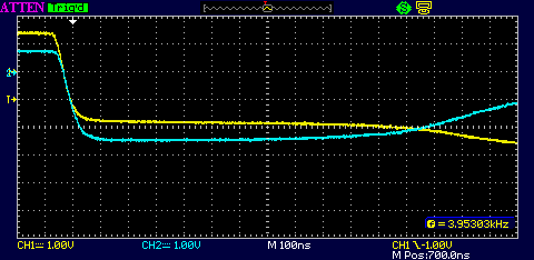
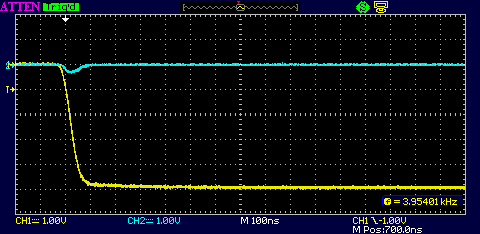
| Raising the DC offset another 100 mV for VF = 700 mV, forward current = 16 mA. The harder the diode is driven into forward conduction, the longer the reverse recovery time. The above plot shows the DUT is conducting for about 1200 ns, with about 600 mV across the junction before it starts turning off. |
This shows how a standard rectifier diode is fine for use at 50 or 60 Hz, where the gradual smooth change into reverse bias takes much longer than the diode's TRR. But you can see that in abrupt switch mode operation, the diode becomes a virtual short circuit for a large percentage of the cycle period. Not good.
Now let's compare the above to a 1N4148.
 |
|
| DC offset adjusted to turn the 1N4148 on hard, VF = 800 mV, IF = 20 mA. There is no measureable reverse recovery time at this edge speed. |
|
 |
|
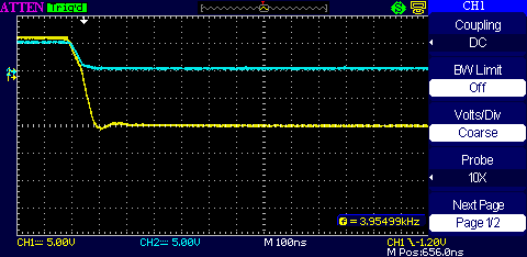
| DC offset and amplitude adjusted to turn the 1N4148 on hard to the limit of the pulse generator, the 50 ohm termination at the DUT input was temporarily removed for maximum forward current of 100 mA, still no measureable reverse current. Note the scale has been temporarily changed to 5 V/div. |
Next let's compare a MUR880.
 |
|
| The MUR880, VF = 0 volts. The higher CJ causes current flow at the falling edge – about 100 pF worth based on the value measured previously for the 120 pF capacitor – better than the data sheet spec of 300 pF. |
|
 |
|
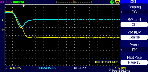
| The MUR880 turned on hard, VF = 600 mV, IF = 20 mA. TRR is about 200 ns as per the data sheet |
|
 |
|
| The MUR880 driven to the limit of the pulse generator as before. IF and IRR are both 100 mA. Scale temporarily changed to 5 V/div. The reverse recovery time is still 200 ns as expected. |
The small TRR makes this diode suitable for high current switchmode use, but even so, one of the limits to the operating frequency is how fast the diodes come out of conduction. Synchronously driven FETs instead of diodes can overcome this limitation.
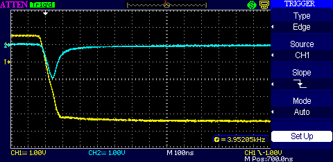
Finally we look at the unknown diode.
 |
|
| The unknown DUT, VF = 0 volts. I temporarily cranked up the blue sensitivity and substituted small capacitors in place of the DUT to find that the DUT CJ is about 25 pF at zero bias. |
|
 |
|
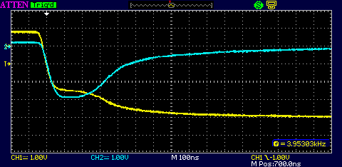
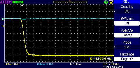
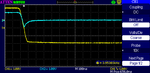
| The unknown DUT turned on hard, VF = 600 mV, IF = 20 mA. TRR is about 100 ns. | |
 |
|
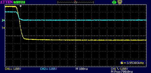
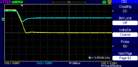
| The unknown DUT, driven to the limit of the pulse generator as before. IF and IRR are both 100 mA. Note the scale has been temporarily changed to 5 V/div. The reverse recovery time is still 100 ns. |
Based on the above measurements, the UF4004 or UF4007 would be a good choice to substitute for the unknown fast-recovery DUT. I told Linda to get both and have Lou try the 1000 V UF4007 first, measure the peak VR, and, if low enough, use the 400 V UF4004 whose forward VI curve more closely matched the unknown.
