William B. Stine, Michael Geyer
Continuation
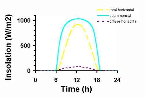
As an example of the importance of the material discussed in Chapter 2, Figure 1.5 shows the variation of insolation over a full, clear day in March at Daggett, California, a meteorological measurement site close to the Kramer Junction solar power plant described previously. The outer curve, representing the greatest rate of incident energy, shows the energy coming directly from the sun (beam normal insolation) and falling on a square meter of surface area which is pointed toward the sun. The peak rate of incident solar energy occurs around 12:00 noon and is 1,030 Watts per square meter. Over the full day, 10.6 kilowatt-hours of energy has fallen on every square meter of surface area as represented by the area under this curve.
 |
|
|
Figure 1.5 |
Insolation data from Daggett, California on a clear March day. |
The middle curve represents the rate of solar energy falling on a horizontal surface at the same location. For reasons to be discussed later, this curve includes both the energy coming directly from the sun's disc, and also that scattered by the molecules and particles in the atmosphere (total horizontal insolation). This scattered energy is shown as the bottom curve (diffuse insolation). Over the entire day, 6.7 kilowatt-hours of solar energy fall on every square meter of horizontal surface, of which 0.7 kilowatt-hours comes from all directions other than directly from the sun.
Techniques for estimating the temporal solar resource at any site on the face of the earth are presented in Chapter 2. In addition, the development and use of computerized meteorological data files is described. These data files based on long-term actual observations, form the time-dependent database of the computerized performance computations contained within this book and, indeed, much of the solar literature.
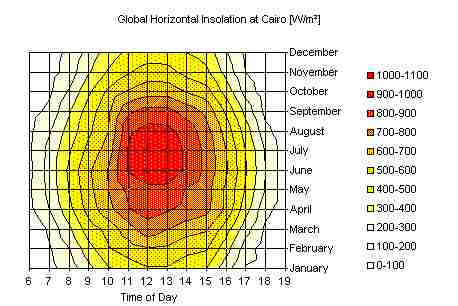
An example of a complete set of beam normal insolation data for a given location is shown in Figure 1.6. Here we see hourly insolation data, summarized over a day, for each month of a year. With this type of data for a specific site, it is possible to predict accurately the output of a solar energy conversion system, whether it is a low temperature thermal system, a high temperature thermal system or a photovoltaic system.
 |
|
| Figure 1.6 | Time and date description of the global, horizontal insolation solar resource for Cairo Egypt. |
In addition to estimating the amount of energy coming from the sun, the solar designer must also be able to predict the position of the sun. The sun's position must be known to predict the amount of energy falling on tilted surfaces, and to determine the direction toward which a tracking mechanism must point a collector. Chapter 3 discusses the computation of the position of the sun with respect to any given point on the face of the earth. Using only four parameters (latitude, longitude, date and local time), equations are derived to determine the location of the sun in the sky.
A characteristic fundamental to the capture of solar energy is that the amount of energy incident on a collector is reduced by a fraction equal to the cosine of the angle between the collector surface and the sun's rays. Knowing the position of the collector (or any other surface for that matter) and the position of the sun equations in Chapter 3 may be used to predict the fraction of incoming solar energy that falls on the collector. These include situations where the collector is fixed or is tracked about a single axis, no matter what the orientation.
1.3 Solar Collectors
The solar collector is the key element in a solar energy system. It is also the novel technology area that requires new understandings in order to make captured solar energy a viable energy source for the future.
The function of a solar collector is simple; it intercepts incoming insolation and changes it into a useable form of energy that can be applied to meet a specific demand. In the following text, we will develop analytical understandings of flat-plate and concentrating collectors, as used to provide heat or electricity. Each type is introduced below.
Flat-plate thermal solar collectors are the most commonly used type of solar collector. Their construction and operation are simple. A large plate of blackened material is oriented in such a manner that the solar energy that falls on the plate is absorbed and converted to thermal energy thereby heating the plate. Tubes or ducting are provided to remove heat from the plate, transferring it to a liquid or gas, and carrying it away to the load. One (or more) transparent (glass or plastic) plates are often placed in front of the absorber plate to reduce heat loss to the atmosphere. Likewise, opaque insulation is placed around the backside of the absorber plate for the same purpose. Operating temperatures up to 125oC are typical.
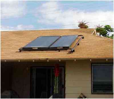
Flat plate collectors have the advantage of absorbing not only the energy coming directly from the disc of the sun (beam normal insolation) but also the solar energy that has been diffused into the sky and that is reflected from the ground. Flat plate thermal collectors are seldom tracked to follow the sun's daily path across the sky, however their fixed mounting usually provides a tilt toward the south to minimize the angle between the sun's rays and the surface at noontime. Tilting flat-plate collectors toward the south provides a higher rate of energy at noontime and more total energy over the entire day. Figure 1.7 shows an installation of flat-plate thermal collectors.
 |
|
| Figure 1.7 | Flat-plate thermal solar collectors for providing hot water. (Pphoto courtesy of DOE/NREL, Warren Gretz) |
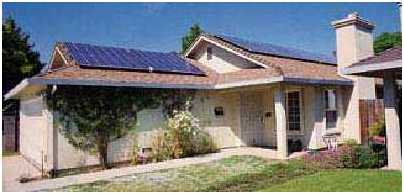
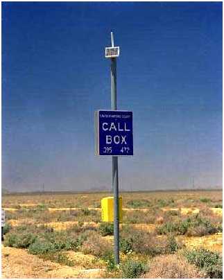
Flat-plate photovoltaic collectors contain an array of individual photovoltaic cells, connected in a series/parallel circuit, and encapsulated within a sandwich structure with the front surface being glass or plastic. Solar energy falls directly upon the photovoltaic cell front surface and produces a small direct current voltage, providing electrical energy to a load. Unlike thermal collectors however, the backside of the panel is not insulated. Photovoltaic panels need to loose as much heat as possible to the atmosphere to optimize their performance.
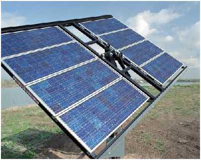
Like flat-plate thermal collectors, flat-plate photovoltaic collectors (panels) absorb both energy coming directly from the sun's disc, and diffuse and reflected energy coming from other directions. In general, flat-plate photovoltaic panels are mounted in a fixed position and tilted toward the south to optimize noontime and daily energy production. However, it is common to see flat-plate photovoltaic panels mounted on mechanisms that track the sun about one tilted axis, thereby increasing the daily output of the panels.
 |
|
 |
|
 |
|
| Figure 1.8 | Flat-plate photovoltaic collector applications. (Pphotos courtesy of DOE/NREL, Warren Gretz) |
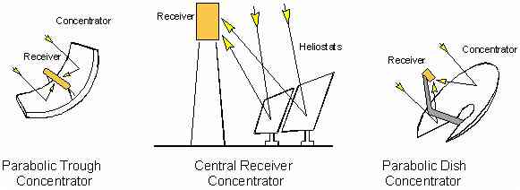
When higher temperatures are required, concentrating solar collectors are used. Solar energy falling on a large reflective surface is reflected onto a smaller area before it is converted into heat. This is done so that the surface absorbing the concentrated energy is smaller than the surface capturing the energy and therefore can attain higher temperatures before heat loss due to radiation and convection wastes the energy that has been collected. Most concentrating collectors can only concentrate the parallel insolation coming directly from the sun's disk (beam normal insolation), and must follow (track) the sun's path across the sky. Four types of solar concentrators are in common use; parabolic troughs (as used in the Kramer Junction, California solar energy electricity generating plant shown in Figure 1.1), parabolic dishes, central receivers and Fresnel lenses. Figure 1.9 shows these concepts schematically.
 |
|
| Figure 1.9 | Three commonly used reflecting schemes for concentrating solar energy to attain high temperatures. |
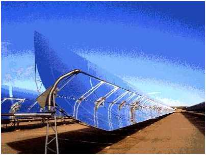
A parabolic trough concentrates incoming solar radiation onto a line running the length of the trough. A tube (receiver) carrying heat transfer fluid is placed along this line, absorbing concentrated solar radiation and heating the fluid inside. The trough must be tracked about one axis. Because the surface area of the receiver tube is small compared to the trough capture area (aperture), temperatures up to 400oC can be reached without major heat loss. Figure 1.10c shows one parabolic trough from the Kramer Junction, California field shown in Figure 1.1.
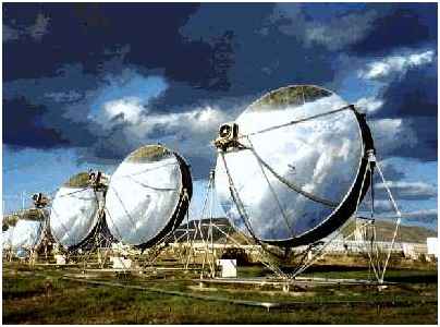
A parabolic dish concentrates the incoming solar radiation to a point. An insulated cavity containing tubes or some other heat transfer device, is placed at this point absorbing the concentrated radiation and transferring it to a gas. Parabolic dishes must be tracked about two axes. Figure 1.10b shows six 9kWe parabolic dish concentrators with Stirling engines attached to the receiver at the focus.
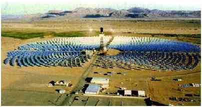
A central receiver system consists of a large field of independently movable flat mirrors (heliostats) and a receiver located at the top of a tower. Each heliostat moves about two axes, throughout the day, to keep the sun's image reflected onto the receiver at the top of the tower. The receiver, typically a vertical bundle of tubes, is heated by the reflected insolation, thereby heating the heat transfer fluid passing through the tubes. Figure 1.10a shows the 10 MWe Solar One central receiver generating plant at Daggett, California with its adjoining steam power plant.
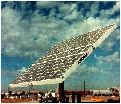
A Fresnel lens concentrator, such as shown in Figure 1.10d uses refraction rather than reflection to concentrate the solar energy incident on the lens surface to a point. Usually molded out of inexpensive plastic, these lenses are used in photovoltaic concentrators. Their use is not to increase the temperature, but to enable the use of smaller, higher efficiency photovoltaic cells. As with parabolic dishes, point-focus Fresnel lenses must track the sun about two axes.
 |
|
| Figure 1.10a | A central receiver system. (Courtesy of Sandia National Laboratories, Albuquerque) |
 |
|
| Figure 1.10b | Two-axis tracking parabolic dish collectors. (Courtesy of Schlaich, Bergermann und Partner) |
 |
|
| Figure 1.10c | A single-axis tracking parabolic trough collector. (Courtesy of Kramer Junction Operating Company) |
 |
|
| Figure 1.10d | A concentrating photovoltaic collector using Fresnel lenses. (Courtesy of Amonix Corp.) |
To be continued
