The project is intended for noncommercial usage only
Paweł Kisielewski
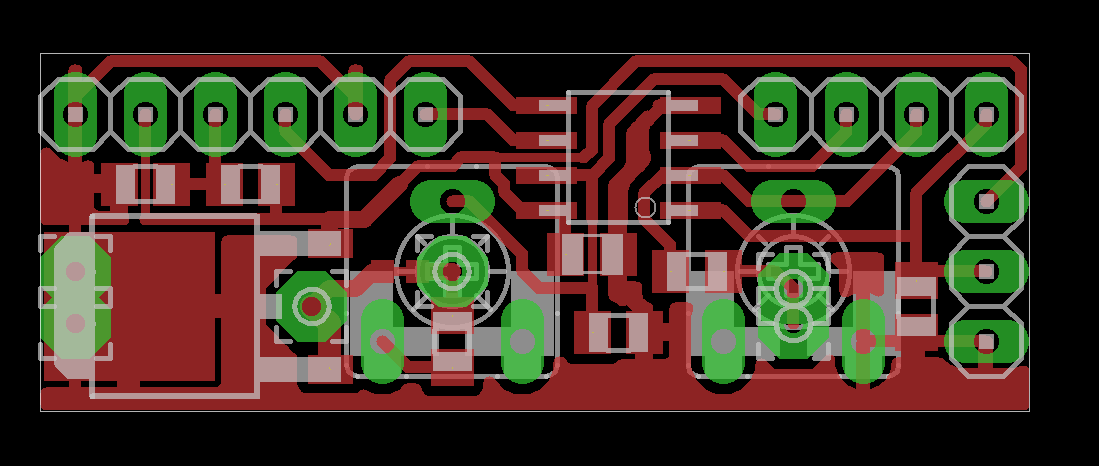
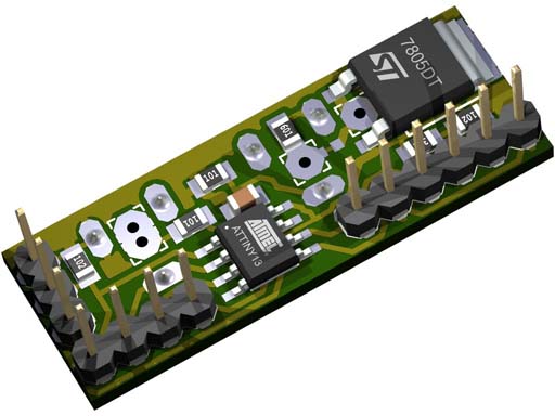
Simple meter on a HD44780 and Attiny13. This project has born from a pure curiosity – what we can made on this small uC? We can, and a lot. In this case this tiny will measure voltage, current, and temperature, recalculate, and in a nice way show on a 16*1 lcd. Despite on unusual solutions and few defects, it still can be used as a power supply meter. PCB dimension – only 35mm x 16mm.
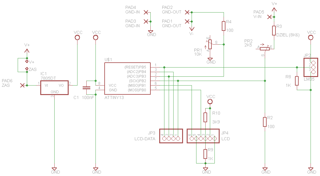
Display uses 6 pins, so we must set the reset pin as normal IO – AFTER programming. Voltage measurement is made by resistor divider, from 0 to 99.9V with 00.1V accuracy. Current made by measuring voltage drop on a 0.1ohm shunt resistor, from 0 to 9.99A with 0.01A accuracy. Temperature made by LM35 analog temperature sensor, from 0 to 99.9*C with 0.01*C accuracy. As measurement voltage reference is used internal attiny13 1.1V vref. So we don’t need to use operational amplifier for current measure (and additional symmetric supply for it), and, calculations are much simpler.
Such simple device have a little defects. Measuring is made on the same pins as LCD data, and LCD takes about 80uA to pull down it’s lines to GND. 100ohm resistor in RR divider can’t properly pull this pin to the GND and it leaves about 7mV referring to GND. This 7mV is simply subtracted from measure result – and we getting to the crux here – results are not be perfect linear, especially in a 0 – 5V range. Remember to use a proper power shunt resistor for higher currents and voltages. Calibrate voltage and current with two troughole potentiometers. LCD contrast is set permanently by two resistors at about 1V – most of LCD’s work good with that value but you can set your own. Current measure is made on ground line. Ground from power supply connect to GND on board, -V is the ground output. Shunt resistor connect between the GND and -V. If you want to supply this device from the same source as the measure point, simply connect it to the +V. Note that the maximum voltage you can give to the 7805 stabilizer is about 30V. So, if you want to measure higher voltages, or measure from 0V, you want to supply this meter from a different source. In that case cut a path under voltage regulation potentiometer, and measure source connect to the +V and then meter supply to the ZAS on board. Board is projected to solder TO252 package 7805 stabilizer, but with no problem you can solder 78L05 in TO92 package. Total current drawn by device, including LCD backlight, is about a 30mA so 78L05 is enough.
Fusebits: enable fusebit RSTDISBL – ATTENTION, make sure you are properly programmed tiny, because after setting that fuse you lose access to the tiny with typical ISP programmer.
ATTACHMENT UPDATED – program tiny13lcd_9_64-sample make 64 samples for each one measurement and display average value.
- eagle 5.4.0 project files,
- schematic and pcb PDF’s,
- PNG,
- firmware HEX, BIN, source BAS.
http://diy.elektroda.eu/category/mikrokontrolery/?lang=en
