Zoltan Gingl
Two configurable analog ports allow you to connect many sensor types using two three-input connectors, each of which has a ground pin (Figure 4). One ground pin provides 3.3V power, and the other outputs the buffered reference voltage – nominally, 2.5V. Wire the central pins of the two connectors to the microcontroller’s analog-input multiplexer. In this way, you can either measure two single-ended voltages or use these two connectors as differential inputs. Both inputs have individually switched pullup and pulldown resistors, R10, R11, R14, and R15.
.gif) |
|
|
Figure 4.
|
You create two configurable analog ports that allow you to connect many sensor types using two three-input connectors, each of which has a ground pin. |
The analog-input architecture allows you to directly connect many kinds of sensors. For example, you can connect a thermistor or a photoresistor between the ground and the input pins and switch on the pullup resistor to form a voltage divider; the on-chip ADC can directly digitize this voltage divider’s output (Figure 5). This approach also features ratiometric operation, meaning that the ADC uses the same reference as the driving voltage of the voltage divider. Current-output sensors can also be connected as you would connect photodiodes – directly between the ground and the input pins. Switch the pulldown resistor so that the photocurrent develops a voltage.
 |
|
|
Figure 5.
|
You could configure analog-input port X1 for a resistive sensor (a) and for a current-output sensor (b), such as a thermistor or a photodiode. |
The high-resolution ADC and PGA allow direct connection of thermocouples (Figure 6). You achieve the required bias point by switching on both the pullup and the pulldown resistors on one channel. You can use directly connected bridge-type sensors, such as load cells and pressure sensors, by switching off all of the internal resistors. In these cases, you should operate the ADC in differential mode. Leaving all of the switches open also suits use in potentiometer inputs or IC sensors, such as the SS49E Hall-effect magnetic-field sensor.
 |
|
|
Figure 6.
|
You can directly connect small-output voltage sensors (a), resistor bridges (b), or IC sensors and potentiometric sensors (c). |
When using directly connected sensors, you should consider source impedance, signal range, filtering, and noise pickup (references 2 and 3). You might need to add external buffer amplifiers or a more precise voltage reference. The availability of a reference voltage and 3.3V power on the analog ports makes this setup possible. You can also use the DAC outputs in connector J1 to trim a value or to provide an arbitrary voltage to the sensors. Note that J1 also has five digital-I/O pins (Part 1, Figure 1).
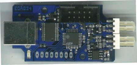
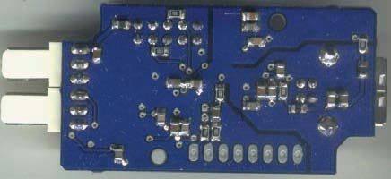
The design fits into a 2.36×1.38-in. enclosure (Figure 7). The underside of the PCB holds several passive components (Figure 8). Reference 4 provides details and enables you to download the entire design, as well as CAD/CAM files, bills of materials, and software.
 |
|
|
Figure 7.
|
The design fits into a 2.36×1.38-in. enclosure. |
 |
|
|
Figure 8.
|
The underside of the PCB holds several passive components. |
References
- Kopasz, Katalin; Peter Makra; and Zoltan Gingl,“Edaq530: a transparent, open-end and open-source measurement solution in natural science education,”European Journal of Physics, Volume 32, February 2011, pg 491.
- C8051F35x Delta-Sigma ADC User’s Guide, Silicon Laboratories, 2005.
- Kester, Walt; James Bryant; and Joe Buxton, “High resolution signal conditioning ADCs,” Analog Devices.
- Gingl, Zoltan, “EDAQ24 24-bit microcontroller sensor-to-USB interface and data logger,” 2011.
Downloads
Schematic and PCB source files, Eagle format (Cadsoft), CAM files (drill, Gerber) - download
Firmware: C source code, Intel hex file (SDCC, Silicon Labs IDE), Configuration file (Silicon Labs Config Wizard) - download
Software: USB driver installer, LabVIEW example and library – download
