Donald Boughton, International Rectifier
EDN
Eliminate errors caused by bias currents and temperature drifts
Analog-circuit design often requires a constant-current sink. An example would be for a TRIAC (tri- ode-for-alternating current) dimmer holding current in fluorescent or solid- state lighting. Other examples include a precise current sink at the end of a long line, such as a cable or an ADSL (asymmetric digital-subscriber-line) modem, which produces a «signature» current value that alerts the device at the source end, such as an exchange office or a cable center, that the remote equipment is attached. The trick is to make a circuit that gives a constant current over a variety of terminal voltages.
A common circuit for achieving this task uses a sense resistor, a transistor, and a power device. Figure 1 shows the circuit using a power transistor, Q1. The circuit provides an approximate constant current at high voltages, but it doesn’t enter regulation until it reaches nearly 60V due to the base current the transistor requires. Figure 2 shows the circuit using a MOSFET, Q1, for the power device. With a MOSFET, you can use smaller biasing resistors, and the circuit comes into regulation at a much lower terminal voltage.
 |
|
| Figure 1. | Resistor R1 sets a constant current through Q1. |
 |
|
| Figure 2. | This circuit substitutes a MOSFET for Q1 in Figure 1 and uses smaller resistors. |
Unfortunately, the current-sense resistor, R1, in Figures 1 and 2 doesn’t sense the bias current. As the terminal voltage increases, the terminal current also increases because of the increased bias current. A simple way to improve the regulation of both circuits is to add resistor R4 and PNP transistor Q3 (Figure 3). R4 and Q3 form a constant-current source to the collector of Q2. The circuit diverts any excess bias current through the collector of Q3 to sense resistor R1. Thus, as the terminal voltage increases, the bias current remains relatively constant, and the current regulation appears much flatter.
 |
|
| Figure 3. | The addition of Q3 and R4 improves current regulation. |
The negative temperature coefficient of the base-to-emitter junction of transistor Q2 causes another problem with this kind of circuit. The temperature coefficient is approximately −1.6 mV/°C, which causes the current value to vary widely with temperature.
 |
|
| Figure 4. | Adding a zener diode improves current regulation over temperature. |
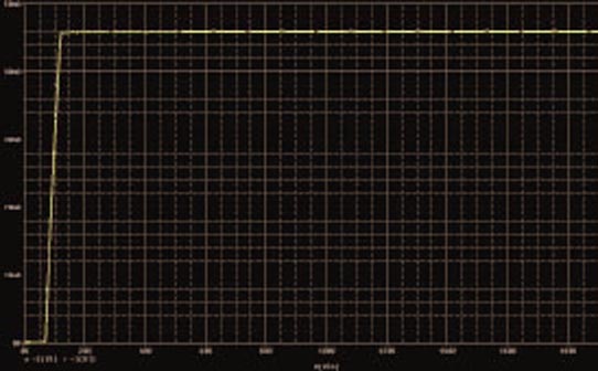
One way to approach this problem is to add a 6.2V zener diode, D1, in series with the emitter of Q2, which increases the sense voltage (Figure 4). A 6.2V diode has a positive temperature coefficient, which counteracts the negative temperature coefficient of the transistor. Furthermore, the total sense voltage is much larger, so 100 mV or so of voltage change with temperature does not seriously affect the regulated current. Figure 5 shows a PSpice simulation of the circuit that uses a MOSFET for Q1.
 |
|
| Figure 5. | A constant current in Q1 has a steep rise relative to VIN. |
