Part 1 - How does RFID work, Whats stored on the card
Part 2 - Schematic and PCB
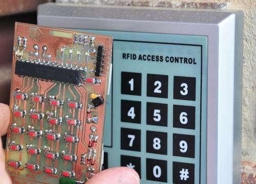
The software was next. Using the Arduino IDE, I implemented a simple menu system that allowed me to enter the relevant facility and CardID data directly from the keypad. I also provided a way of displaying the data using the LEDs that I mounted on the board.
One problem I came across, was when I was calculating the card data (parity and checksum) on the fly - To be read successfully, the card has to output data in real time (most readers need a number of sequential valid reads), and adding subroutine and calculation delays caused the card to output invalid data as far as the reader was concerned. I worked around this problem by populating an array of bits that gets sent when the card is in transmit more. That way, the calculations are done only once.
How does the parity and checksum work?
One final piece of data that the card transmits is a checksum word - this is used to ensure that all of the data has been received successfully. Firstly, the parity bit at the end of each nibble of data is Even parity - this means that the transmitter will add a 1 to make sure that each block of data has an 'even' number of '1' bits - So if we look a the '2', which is 0010 in binary - the parity system would detect that there was an odd number of '1' bits, and would add one to compensate. Compare that to the 'C' which is 1100, the parity system would detect that there are an even number of '1' bits, so it would add a zero.
|
BIN
|
HEX
|
|
00101
|
2
|
|
11000
|
C
|
|
00000
|
0
|
|
00000
|
0
|
|
01111
|
7
|
|
01111
|
7
|
|
01010
|
5
|
|
01010
|
5
|
|
10100
|
A
|
|
00101
|
2
|
|
Checksum
0110 |
Finally, the checksum is an even parity bit applied to each of the vertical row bits. This way, there is a horizontal and vertical check of every bit sent - everything has to line up, or the reader will simply reject the transmission.
When I decoded the data for my work prox card, it followed a similar sequence here, but (for obvious reasons) I won't actually publish the numbers. Again, part of the sequence was a facility code, and the rest of the sequence held the same number that was printed on the back of the card.
When the card is powered up, it waits for the 'mode' button to be pressed. The current mode number is displayed using a set of 4 LEDs. Each press on the 'mode' button increments the current mode. Once the correct mode is displayed, then the 'enter' key starts that function executing.
- MODE 1 - Enter low power (sleep) mode
The card enters a low power mode, waiting for the reset button to be pressed to re-awaken it
- MODE 2 - Enter a Hex Facility ID
The card waits for 2 digits to be entered signifying the facility code for this system (In this case, it is 2C) - The software defaults to 2C - so this does not need to be entered.
- MODE 3 - Decimal Card ID
The card waits for 8 digits to be entered signifying the CardID for the card to be spoofed (In this case, it is 07820706) - This is the long number printed on the back of the card, not the 119,21922 number.
- MODE 4 - Dump the facility and Card ID
The Facility and Card ID are Dumped as Hex numbers using the 4 Leds at the top of the card.
- MODE 5 - Emulate a card
The card enters emulation mode - all LEDs are turned off. Emulation mode can only be exited by pressing the reset button.
I used a standard 6 pin header mounted on the PCB to allow a FTDI 5V USB-232 cable to be used to program the chip in-situ - this was especially important, as the ATMega chip is soldered directly to the PCB, so it couldn't be removed for insertion into a normal Arduino PCB- This is a small price to pay to have a nice compact project.
The chip was programmed using the .pde Arduino sketch using the normal Arduino IDE. The .PDE file that I have provided is tailored to the standard cheap eBay RFID systems.
Testing was a breeze - I typed the relevant code into the keypad, swiped the board against the reader, and was rewarded with a satisfying 'BEEP' indicating that the read was successful.
Downloads
Arduino Sketch - download
