Part 1 - Theory
Part 2 - Schematic, Firmware for the PIC microcontroller to initialize the GLCD
In the first part of this tutorial, we discussed about Winstar’s WDG0151-TMI GLCD module, which is a 128×64 pixel monochromatic display built with KS0108B and KS0107B compatible display controllers. The module was interfaced to a PIC16F887 microcontroller and a test program was written in C to demonstrate how to implement the KS0108 instruction set in the firmware of PIC to activate display pixels on the screen. We wrote our subroutine programs that would turn the GLCD on, move the display location to a specified row and column, and draw a pixel at a given coordinates. You might have realized it by now that how much of effort is required to write the firmware for just plotting a point on a GLCD screen. Today’s discussion will focus more on using the built-in GLCD library routines of mikroC Pro for PIC compiler, which will make your life a lot easier if you are using a graphical LCD in your project.
GLCD Library of mikroC Pro for PIC
The mikroC Pro for PIC provides GLCD library for a 128×64 pixel graphical LCD with Samsung KS0108/KS0107 controller chips. The library routines are categorized into two types: basic and advanced. Before using any library routine, following pin definitions is required. For our case (see the circuit diagram in the first part) where PORTD is used for data and PORTB pins for control signals, the GLCD pin settings should be defined as follows. Remember that the data lines must be on a single port.
// glcd pinout settings
   char GLCD_DataPort at PORTD;
   sbit GLCD_CS1 at RB0_bit;
   sbit GLCD_CS2 at RB1_bit;
   sbit GLCD_RS at RB2_bit;
   sbit GLCD_RW at RB3_bit;
   sbit GLCD_EN at RB5_bit;
   sbit GLCD_RST at RB4_bit;
   sbit GLCD_CS1_Direction at TRISB0_bit;
   sbit GLCD_CS2_Direction at TRISB1_bit;
   sbit GLCD_RS_Direction at TRISB2_bit;
   sbit GLCD_RW_Direction at TRISB3_bit;
   sbit GLCD_EN_Direction at TRISB5_bit;
   sbit GLCD_RST_Direction at TRISB4_bit;
Basic routines:
- Glcd_Init : Initializes the Glcd module
- Glcd_Set_Side: Selects the Glcd side. Example, Glcd_Set_Side(0) and Glcd_Set_Side(62) both select the left side of the GLCD. Values from 64-127, such as Glcd_Set_Side(67), selects the right side of the GLCD.
- Glcd_Set_X : Sets x-axis position from the left border of Glcd within the selected side. Example, Glcd_Set_X(25).
- Glcd_Set_Page : Selects page (0-7) of the Glcd.
- Glcd_Read_Data : Reads one byte of data from the current location of Glcd memory and moves to the next location.
- Glcd_Write_Data : Writes one byte of data from the current location of Glcd memory and moves to the next location.
Advanced routines:
- Glcd_Fill : Fills GLCD display RAM with a byte pattern. If the byte is 0, it will clear the display. If it is 0xFF, then it will fill the entire display with 1.
- Glcd_Dot : Draws a dot on Glcd at given coordinates with a specified color. It is used as Glcd_Dot(x, y, color), where x = 0-127, and y=0-63, and color = 0-2. The parameter color determines a dot state: 0 clears dot, 1 puts a dot, and 2 inverts the dot state.
- Glcd_Line : Draws a line joining two specified point coordinates and a given color value (0-2).
- Glcd_V_Line : Draws a vertical line passing through two points with the same x-coordinate. It also accepts color parameter.
- Glcd_H_Line : Draws a horizontal line passing through two points with the same y-coordinate. It also accepts color parameter.
- Glcd_Rectangle : Draws a rectangle with specified top left and bottom right corner coordinates. It also accepts color parameter.
- Glcd_Box : Draws a box with specified top left and bottom right corner coordinates. Unlike in Glcd_Rectangle, the color parameter here is the fill color of the box.
- Glcd_Circle : Draws a circle with specified center coordinates and radius. It also accepts color parameter.
- Glcd_Set_Font: As it was mentioned earlier in Part1, KS0108 controller does not have a built-in character generator and therefore fonts must be written in the firmware of the external microcontroller. This is a time consuming task as you need to determine data values for each letter to display. For simplicity, mikroElektronika provides the following demo fonts with mikroC Pro for PIC compiler.
- Font_Glcd_System3x5
- Font_Glcd_System5x7
- Font_Glcd_5x7
- Font_Glcd_Character8x7
These fonts are used by Glcd_Write_Char and Glcd_Write_Text functions (defined below) to display character and text. The syntax for defining font is,
Glcd_Set_Font (const char *activeFont, unsigned short aFontWidth, unsigned short aFontHeight, unsigned int aFontOffs);
where parameters are:
- activeFont: font to be set. Needs to be formatted as an array of char
- aFontWidth: width of the font characters in dots.
- aFontHeight: height of the font characters in dots.
- aFontOffs: number that represents difference between the mikroC PRO for PIC character set and regular ASCII set. Demo fonts supplied with the library have an offset of 32.
So, if you want to use the Font_Glcd_5x7, you can define the font as,
Glcd_Set_Font(Font_Glcd_5x7, 5, 7, 32);
- Glcd_Write_Char : Writes a character at a defined x-position (0-127) and page number (0-7) on GLCD.
- Glcd_Write_Text : For printing a text at a given x-position (0-127) and page number (0-7) on GLCD
- Glcd_Image: Displays bitmap image on Glcd. The bitmap array of the image must be provided in the firmware.
Circuit diagram
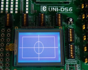
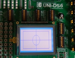
It is the same as described in Part 1 of this tutorial and I am using UNI-DS6 development board for demonstration.
Software
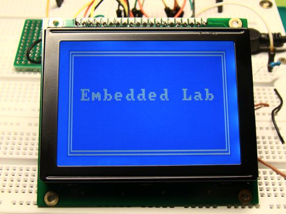
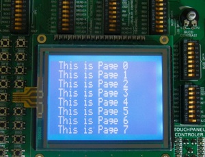
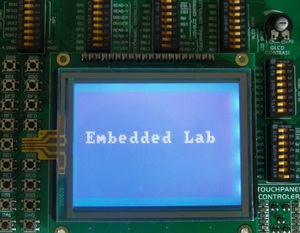
The following program is written in mikroC Pro for PIC compiler for demonstrating the GLCD library routines described above. The first part of the program draws horizontal and vertical lines, rectangle, circle, and a filled box on the GLCD. The second part writes texts in all eight pages (0-7) using Font_Glcd_5x7. At the end, bigger font size (Font_Glcd_Characters_8x7) is used to write “Embedded Lab” at the center of the screen.
 |
 |
 |
 |
Downloads
Source code an HEX - download
