This project describes an easy and inexpensive way of adding a digital thermometer and data logging feature to a PC. It involves a PIC microcontroller that gets the surrounding temperature information from the Microchip MCP9701 sensor, and sends it to a PC through an USB-UART interface. The USB port of the PC is also used to power the device. The open-source Processing programming platform is used to develop a PC application that displays the temperature in a graphics window on the computer screen. The PC application also records the temperature samples plus date and time stamps on an ASCII file.
Theory of operation
This project is based on Microchip’s PIC12F1822 microcontroller from the enhanced mid-range PIC family. It has got 8-pins in total and the power supply voltage range of 1.8V to 5.5V. The microcontroller has four 10-bit ADC channels and one Enhanced Universal Synchronous Asynchronous Receiver Transmitter (EUSART) module for serial communication. The temperature sensor used here is MCP9701A, which is a Low-Power Linear Active Thermistor IC from Microchip Technology. The range of temperature measurement is from -40°C to +125°C. The output voltage of the sensor is directly proportional to the measured temperature and is calibrated to a slope of 19.53mV/°C. It has a DC offset of 400mV, which corresponds to 0°C. The offset allows reading negative temperatures without the need for a negative supply. The output of the sensor is fed to one of the ADC channels of the PIC12F1822 microcontroller for A/D conversion. The internal fixed voltage reference (FVR) module is configured to generate a stable 2.048 V reference voltage for A/D conversion. The use of FVR module ensures the accuracy of the A/D conversion even when the supply voltage is not stable. The PIC12F1822 microcontroller then serially transmits the 10-bit ADC output to a PC.
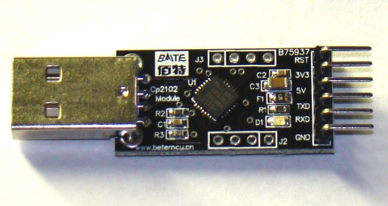
Modern PCs are no more equipped with serial ports and therefore this project requires a USB-UART adapter that enables very easy connection of the PIC12F1822 to the PC via the USB port. You can get them really cheap on ebay. It can be directly interfaced to the TTL input and output of EUSART module of PIC12F1822. This module also provides +5 V, +3.3 V, and ground terminals. The power supply for the microcontroller circuit is derived from the same +5 V and ground pins.
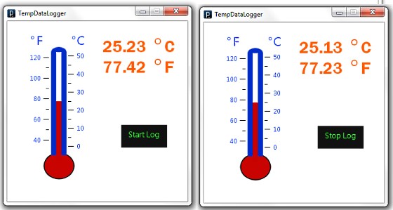
On PC’s side, the open source programming language Processing is used to receive the ADC output and convert it into the actual temperature. The temperature is displayed on a graphics window on the computer screen in numeric format as well as with a wall tube thermometer looking image where the level of alcohol rises with increasing temperature. A clickable Start/Stop button also appears on the window to enable or disable the data logging.
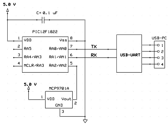
Circuit diagram
The circuit diagram of this project is pretty simple. The microcontroller reads the temperature sensor’s output through RA2/AN2 pin and convert it to a 10-bit digital number. The Tx (RA0) and Rx (RA1) port of the EUSART module are connected to the corresponding pins of the USB-UART module. The microcontroller runs at 4.0 MHz using an internal clock source. Although I have disabled the MCLR function here, you can use it for an external reset if you want.
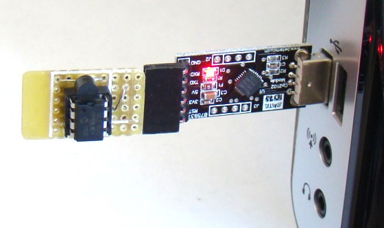
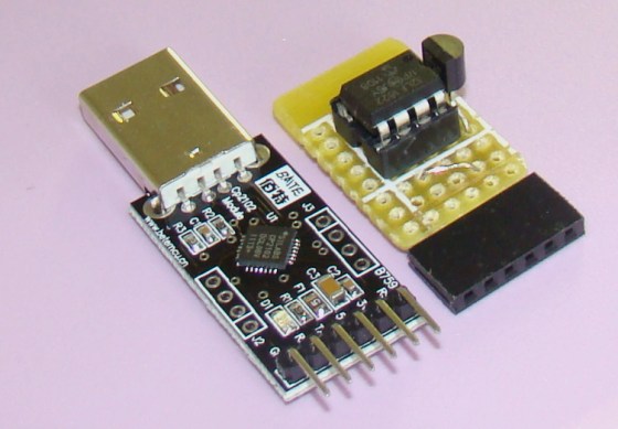
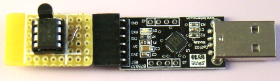
I soldered the above circuit (except the USB-UART adapter) on a general purpose prototyping board with a 6-pin female header connector so that it could be easily plugged into the male header pins of the USB-UART adapter (shown below).
Software
The firmware for PIC12F1822 is developed in C and compiled with mikroElektronika’s mikroC Pro for PIC compiler. The compiler does provide an ADC library but that uses the external supply voltage as a reference for A/D conversion. In order to configure the FVR module to generate a fixed 2.048V for A/D conversion, you have to write your own code for ADC operation. The ADC sample is taken every 2 sec and is sent to the PC through USB-UART module as two bytes. The complete source code is provided below with comments. It can be compiled with the demo version of mikroC Pro for PIC compiler. Make sure that you select the internal clock source at 4.0 MHz from Project->Edit window.
As I mentioned earlier, the PC application is developed using the Processing programming language. Processing is an open-source software development environment designed for simplifying the process of creating digital images, animations and interactive graphical applications. It is free to download and operates on Mac, Windows, and Linux platforms. I have written a simple application here that receives the 10-bit ADC sample from the serial port, converts it to temperature, and display it on the computer screen. The Processing serial library allows for easily reading and writing data to and from the serial ports.
Conversion formula for MCP9701A
Resolution of A/D conversion (Vref = 2.048V) = 2.048 V/1024 = 2 mV/count
Equivalent voltage for 10-bit ADC output (Count) = 2*Count (mV)
Temperature (°C) = (Voltage – Sensor Offset)/Sensor conversion coefficient,
where Sensor Offset = 400 mV and conversion coefficient = 19.5 mV/°C from datasheet.
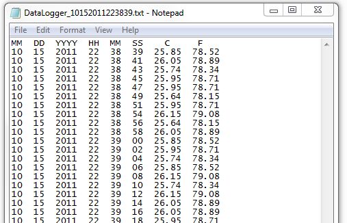
A clickable Start/Stop button is also provided on the display window. The Processing Mouse functions are used to detect a mouse press over the button. When the Start is pressed, data logging begins and the label on the button turns into ‘Stop’. If Stop is pressed, the data logging is paused. The temperature samples are recorded along with the date and time stamp (from PC) into an ASCII file. Every time the Start is pressed, the program creates a new ASCII log file. The name of the file contains the current system date and time so that there won’t be any overwriting of files. However, the data are temporarily stored into the PC’s RAM and are transferred to the ASCII file on the hard drive only after pressing the Stop button.
Future enhancements
There is a lot of room for improvements in this project. The sampling interval of the data logger is currently hard coded into the firmware of the PIC12F1822 microcontroller. However, both the firmware and the PC application can be modified to make the sampling time user-configurable from the application window. Similarly, a plotting program can also be added to the Processing application to display the temperature profile from the logged files.
Conversion formula for MCP9701A
Resolution of A/D conversion (Vref = 2.048V) = 2.048 V/1024 = 2 mV/count
Equivalent voltage for 10-bit ADC output (Count) = 2*Count (mV)
Temperature (°C) = (Voltage – Sensor Offset)/Sensor conversion coefficient,
where Sensor Offset = 400 mV and conversion coefficient = 19.5 mV/°C from datasheet.
Downloads
Source code (mikroC) - download
Processing source code and exported applications - download
