Eliminating excess noise from an oscilloscope probe yields better measurements
You must minimize noise when measuring ripple in power rails because the ripple’s amplitude can be low. Oscilloscope probes are essential measurement tools, but they can introduce noise and errors. Ground leads, such as those that attach to standard oscilloscope probes, can add noise that’s not present in your circuit to an oscilloscope’s trace. The wire loop acts as an antenna that picks up stray magnetic fields. The larger the loop area, the more noise it picks up. To prove this theory, connect the oscilloscope ground lead to the probe tip and move it around. The oscilloscope will show the noise increasing and decreasing with the ground-lead movement. You can use an oscilloscope probe with its ground lead and sockets to build a simple interconnect board (Figure 1).
 |
|
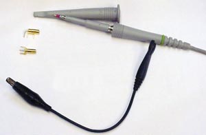
| Figure 1. | A standard oscilloscope probe has a ground lead that can pick up noise. |
Start by removing the probe’s cover, which reveals the probe tip. There is a short distance between the tip and the ground ring. You need one of two sockets: a right-angle, or horizontal, socket or a vertical socket, similar to those in Figure 1. Solder the center leg of the socket to the output of the power supply and solder the other leg to the power-supply return. Connect a 0.1-μF surface-mount, stacked ceramic capacitor between the two sockets. This step limits the probe bandwidth to approximately 5 MHz, which further reduces high-frequency noise and lets the lower-frequency ripple pass through. Figure 2 shows the completed interconnect board, and Figure 3 shows a schematic of the board. Insert the probe tip into the socket to measure ripple. You will get a ripple measurement without spikes or other noise.
 |
|
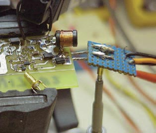
| Figure 2. | Solder wires from the power supply under test to an interconnect board reduce ground-lead length. |
 |
|
| Figure 3. | A ceramic capacitor further reduces high-frequency noise. |
You should use a multilayer stacked ceramic capacitor because it’s better at decoupling high-frequency noise. Electrolytic, paper, and plastic-film capacitors comprise two sheets of metal foil. A sheet of dielectric separates the metal-foil sheets, and these three components form a roll. Such a structure has self-inductance; thus, the capacitor acts more like an inductor than a capacitor at frequencies higher than a few megahertz. Figure 4 shows the impedance to the power supply for various stacked-ceramic-capacitor values.
 |
|
| Figure 4. | Probe impedance varies with capacitor value. |
