Controlling temperature has been a prime objective in various applications including refrigerators, air conditioners, air coolers, heaters, industrial temperature conditioning and so on. Temperature controllers vary in their complexities and algorithms. Some of these use simple control techniques like simple on-off control while others use complex Proportional Integral Derivative (PID) or fuzzy logic algorithms. In this project I’m going to discuss about a simple control algorithm and utilize it intelligently unlike analogue controllers.
|
|
|
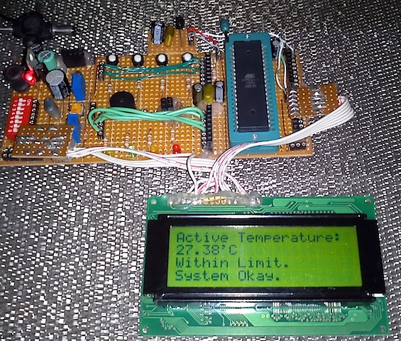
| Figure 1. | Intelligent temperature monitoring and control system using AVR microcontroller. |
Here are the features of our controller:
- Audio-visual setup for setting temperature limits.
- Fault detection and evasive action.
- Temperature monitoring and display.
- Audio-visual warning.
- System status.
- Settable time frame.
- Data retention with internal EEPROM memory.
Intelligent temperature controller
For this design I used an Atmel AVR ATMega32L AVR microcontroller with an internal clock frequency of 8MHz, a 4×20 LCD for presenting data visually, a 4-button input interface, a tiny piezo sounder for audible indications and some LEDs for showing faults and simulating real-life devices like heater and coolers. I used MikroC for AVR compiler from Mikroelektronika to develop the firmware for this controller.
Hardware
|
|
|
| Figure 2. |
Intelligent temperature monitoring and control system: Microcontroller and display circuit |
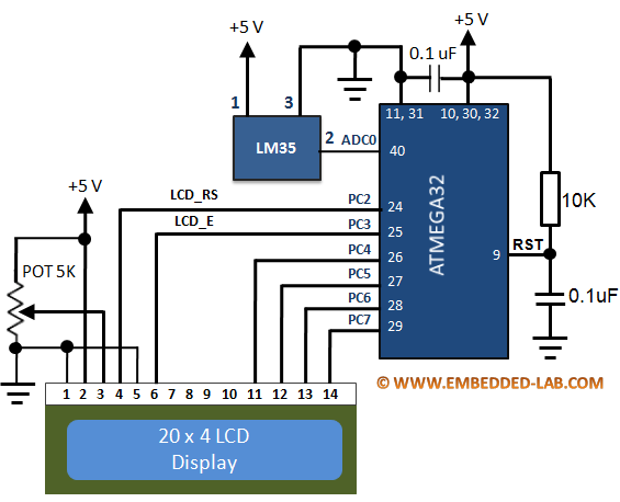
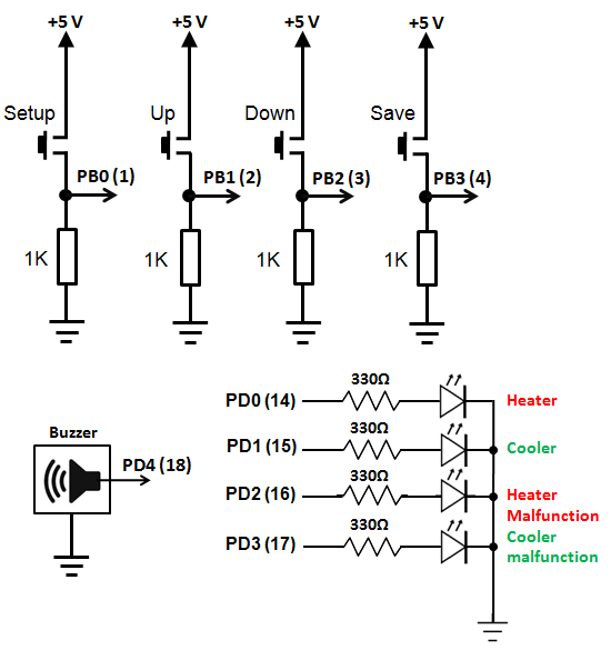
The hardware consists of a four-button interface, four LEDs, a piezo tweeter or sounder, a 4×20 LCD, a LM35 temperature sensor, an AVR ATMega32L microcontroller and some other passive parts. Two LEDs connected to PORTD0 and PORTD1 pins simulate on and off operation of relay switches that are actually present in actual applications to control a heater and an air conditioner. The hardware is powered by a 5V source preferably with a 5V regulator like 7805. If relays are used then a 12/24V source will also be needed to power the relays. The AVR micro’s AVREF and AVCC pins should be both connected to the 5V source. The distance between the LM35 sensor and the AVRs ADC pin must not be greater than 10-12cm for proper temperature reading. Though I did this project in a prototyping board made with a strip board, a PCB version is more preferred. Two additional LEDs connected to PD2 and PD3 indicates the failure or malfunctioning status of the air conditioner and the heater.
|
|
|
| Figure 3. | Intelligent temperature monitoring and control system: Input/Output circuit |
Part 2 - Firmware
