The idea behind this post is to bring together some robot designs and trasform them in a new device with new hardware and standard software (arduino of course) and so easier to use. These robots have three things in common: a mechanical structure, the hardware and the software. While the mechanical part is necessarily different, we wanted to understand if there was a hardware board that could be common, with a unique development system. The choice, quite obviously, has the Arduino board, which with its development environment is perfect to create similar projects.
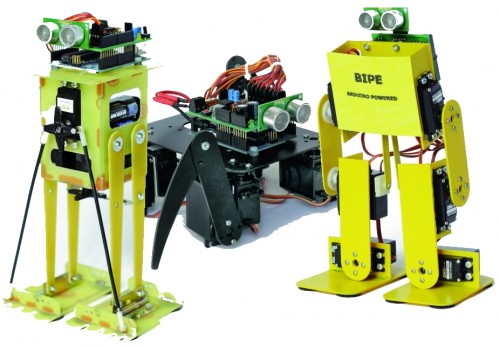
The Robot are three, corresponding to the robots Filippo, Bipe and Spider.
The first consideration that came to our mind is like the Arduino board can manage a large number of servos, eight in the case of the robot SPIDER. Arduino can be powered through the plug with a voltage between 6 to 12 volts, his voltage regulator provides the 5 V stabilized, necessary for the operation of our shield. We could power our robot with rechargeable batteries. A standard servo requires a supply voltage of 4.8 to 6 volts, easily obtainable with four batteries in series, at full charge, provide 1.5 x 4 = 6 volts but towards the complete discharge provide just 1.0 x 4 = 4 volts. We are not in optimal conditions for the servos. Throughout this reasons we decided to create a special shield, already prepared for all these functions, it is easy to install and use.
We see now the considerations that led us to the design of this shield:
- must have a high voltage range
- will provide a stabilized output for the servos
- will provide power to the Arduino
- must be equipped with an obstacle sensor
- must have a receiver for remote control
- must read the battery
We can assume to power our robot with a single battery pack with a voltage between 6 and 12 volts, so for example two cells or 6-8 LiPo NiMh or NiCd cells. The servos works at 5Volt, so we should get this stabilized voltage starting from input voltage of 6-12 volts. The optimal solution is the use of a switching step-down regulator which ensures efficiency exceeding 80% in every situation.
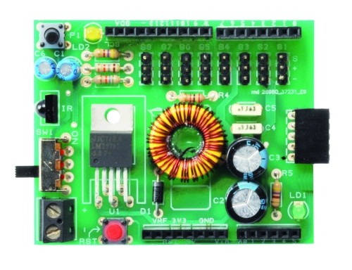
Just the integrated LM2576-5 contains all the elements to build a switching power supply, just add an inductor, a diode and a capacitor. It can deliver a maximum current of 3A and accepts input voltages between 4 and 40volt.
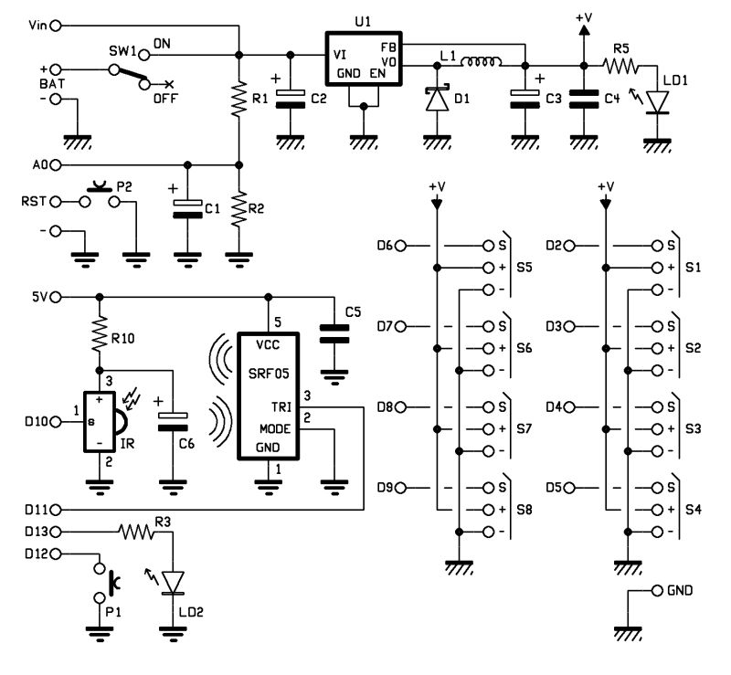
Analysing the wiring diagram you can see the connector BAT which will connect the battery pack to the switch and the voltage regulator LM2576, the resistance R5 and the led LD1 are used only to detect the presence of the voltage. The stabilized voltage output from the LM2576 will be used to power all the servos, while the Arduino is powered directly from the battery pack, taking the tension just after the switch (Vin).
For reading the battery voltage will use an analog input of Arduino (A0). The two resistors R1 and R2 reduce the voltage to a value between 0 and 20 volts to a value of 0-5Volt. We chose these specific values of resistance because, by reading the analog voltage with Arduino, it is sufficient to divide the data acquired by 50 to obtain the value of the voltage in volts.
As obstacle sensor we chose the ultrasonic sensor model SRF05 that, thanks to its shape, recalls two eyes and improves the aesthetic appearance of our robot. To operate, we use a digital line connected to PIN11.
As remote control we opt for a economical infrared system; is sufficient to install an IR receiver compatible with the normal commercial remote controls, such as the integrated PNA4602. It will be sufficient a normal remote control of those used for TVs or VCRs to send commands to our robot in a simple and economic way. The shield provides the Arduino reset button, a button for general use and a LED connected to pin 13 of Arduino.
BOM
R1: 56 kohm
R2: 18 kohm
R3: 470 ohm
R4: 100 ohm
R5: 470 ohm
C1: 10 µF 63 VL
C2: 470 µF 25 VL
C3: 1000 µF 16 VL
C4: 100 nF
C5: 100 nF
C6: 10 µF 63 VL
LD1: LED 3 mm red
LD2: LED 3 mm green
U1: LM2576-5
SW1: switch
P1: Microswitch
RST: Microswitch
IR: IR38DM
L1: 100 µH 2A
D1: 1N5819
SRF05: SRF05
Downloads
Gerder for Shield - download
Part 2 - Robots Filippo, Bipe and Spider
