By Don Nisbett, Analog Devices
As a vital part of modern cars, wiring harnesses containing thousands of assembly components connect various electronic systems, enabling them to work together. A single failure in any harness can affect the entire system. Nevertheless, to accommodate the growing demand for in-car electronics, the complexity of automotive wiring harnesses continues to grow, increasing the need to detect broken or shorted wires quickly and easily. Wire diagnostics are important throughout the entire life of the car. Starting with the installation phase, diagnosing and repairing wiring faults can cause extensive manufacturing delays. During the operational phase, diagnosing and repairing wiring faults can cause prolonged visits to the repair shop, adding significant costs to manufacturers in the form of warranty repairs.
Active safety systems, including lane detection and parking assist (front and rearview cameras) – and infotainment systems, including navigation and rear seat entertainment – are some of the more highly sought automotive electronics systems. For these systems to be effective, video data transmitted via cable from all corners of the car must reliably get to the driver and passengers. Cable health is crucial for maintaining proper operation of these systems.
This article offers a circuit idea that provides a robust, cost-effective technique for implementing wire diagnostics on the video and audio transmission lines in automotive applications.
 |
|
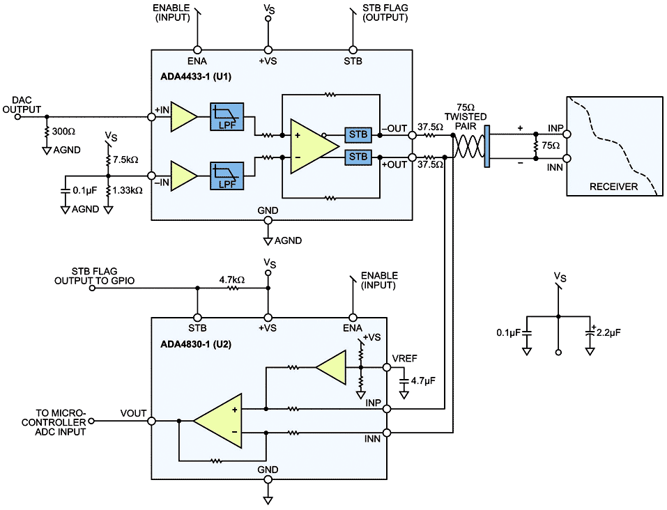
| Figure 1. | Wire diagnostic circuit using the ADA4433-1 (U1) and ADA4830-1 (U2). |
The circuit shown in Figure 1 can effectively detect short-to-battery (STB), short-to-ground (STG), open-circuit, and short-circuit faults. The circuit uses an ADA4433-1 (U1) fully integrated video reconstruction filter as part of the video transmission signal chain and an ADA4830-1 (U2) high-speed difference amplifier as the detection circuit. The ADA4433-1 features a high-order filter with a −3-dB cutoff frequency of 10 MHz, 45-dB rejection at 27 MHz, and an internally fixed gain of 2 V/V. It has excellent video specifications, overvoltage protection (STB) and overcurrent protection (STG) on its outputs, and low power consumption. The ADA4830-1 provides an attenuating gain of 0.50 V/V and a fault detection output flag that can indicate the presence of an overvoltage condition on its inputs. It features input overvoltage protection of up to 18 V, a wide common-mode input voltage range, and excellent ESD robustness.
In the example circuit shown in Figure 1, U1 represents the differential output buffer that transmits the video signal from a rearview camera or engine control unit (ECU) to the receiver. The input would typically be driven by a CMOS imager or video encoder. The primary function of U1 is to provide the active filtering function (reconstruction) and to drive the video signal through the cable to the display. The inputs of U2 are connected across the outputs of U1 to provide the fault detection features listed in Table 1 and described in the following paragraphs.
Table 1. Summary of Diagnostic Output Indicators
|
Fault Condition
|
U1 Input
Configuration |
U2 Output
Indicator |
Voltage Level
at Indicator |
|
Short to Battery
|
|
Pin 5
|
85 mV
|
|
Short to Ground (Single Output)
|
INP = INN
|
Pin 6
|
530 mV
|
|
Short to Ground (Both Outputs)
|
INP ≠ INN
|
Pin 6
|
10 mV
|
|
Open Circuit
|
INP ≠ INN
|
Pin 6
|
500 mV
|
|
Short to Adjacent Output
|
INP ≠ INN
|
Pin 6
|
0 mV
|
| Normal Operation (No Cable Faults) |
|
Pin 6
|
250 mV
|
Short-to-Battery Fault Detection
Both U1 and U2 have integrated short-to-battery detection and an STB output flag. During a short-to-battery event, the output flag of U2 will signal a logic low that can be easily read by a micro-controller’s general-purpose input/output port.
Short-to-Ground Fault Detection (Single Output)
Connect the positive input (INP) of U1 to the negative input (INN). The differential output between +OUT and −OUT should be 0 V. If either output is shorted to ground, the differential voltage at the output of U2 will be greater than 500 mV.
Short-to-Ground Fault Detection (Both Outputs)
Set the positive input (INP) of U1 to 0 V. The differential output between +OUT and −OUT should be approximately 1 V. If both outputs are shorted to ground, the differential voltage at the output of U2 will be approximately 0 V.
Open Circuit
Set the positive input (INP) of U1 to 0 V. The differential output between +OUT and −OUT should be approximately 1 V. If there is an open connection, the resulting differential voltage at the output of U2 will be approximately 500 mV.
Short to Adjacent Output
Set the positive input (INP) of U1 to 0 V. The differential output between +OUT and −OUT should be approximately 1 V. If both outputs are shorted together, the differential voltage at the output of U2 will be approximately 0 V.
Normal Operation (No Cable Faults)
Set the positive input (INP) of U1 to 0 V. The resulting differential output between +OUT and −OUT should be approximately 1 V. The resulting differential voltage at the output of U2 will be approximately 250 mV.
