Application Note AN142
November 2013
Christian Kueck
Switching regulators replace linear regulators in areas where low heat dissipation and efficiency are valued. The switching regulator is typically the first active component on the input power bus line, and therefore has a significant impact on the EMI performance of the complete converter circuit.
Modern input filter components in surface mount technology have better performance than through-hole parts. However, this improvement is outpaced by the increase in operating switching frequencies of switching regulators. Higher efficiency, low minimum on- and off-times result in higher harmonic content due to the faster switch transitions.
For every doubling in switching frequency the EMI becomes 6 dB worse when all other parameters, such as switch capacity and transition times, remain constant. The wideband EMI behaves like a first order highpass with 20 dB higher emissions if the switching frequency increases by 10x.
Savvy PCB designers will make the hot loops small and use shielding GND layers as close to the active layer as possible; nevertheless pinout, package construction, thermal design requirements and package sizes needed for adequate energy storage in decoupling components dictate a certain minimum hot loop size.
To make layout even more challenging, on a typical planar printed circuit board the magnetic or transformer style coupling between traces above 30 MHz will diminish all filter efforts, since the higher the harmonic frequencies are, the more effective unwanted magnetic coupling becomes.
The tried and true solution is to use a shielding box for the complete circuit. Of course, this adds costs, increases required board space, makes thermal management and testing more difficult, and introduces additional assembly costs. Another frequently used method is to slow down the switching edges. This has the undesired effect of reducing the efficiency, increasing minimum on-, off-times, as well as the required dead times, and compromises the potential current control loop speed.
![]() Download Application Note AN142 (159 Kb)
Download Application Note AN142 (159 Kb)
Related datasheets:
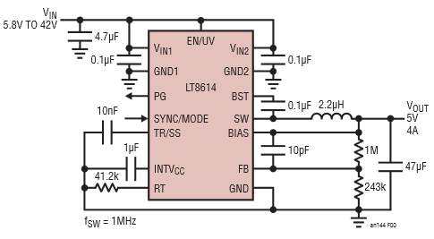
The LT8614 Silent Switcher Minimizes EMI/EMC Emissions While Delivering High Efficiency at Frequencies Up to 3 MHz
