Martin Jagelka, Martin Daricek & Martin Donoval
EDN
Continuous monitoring of heart activity permits measurement of heart rate variability (HRV), a basic parameter of heart health and other diseases.
This Design Idea is a new design of pulse oximetry that excels in its simplicity and functionality. Due to its capabilities, it can be used as a standalone device, able to monitor heart rate and oxygen saturation.
The core of the system is composed of the ultra-bright red LED (KA-3528SURC), infrared LED (VSMB3940X01-GS08), and a photodiode (VBP104SR) sensitive to both wavelengths of light at the same level (Figure 1).
 |
|
| Figure 1. | Pulse oximeter. |
The basic building block of the system is operational amplifier LT6003, which is used in several stages. IC1 is used as a transimpedance amplifier, converting the current generated by the photodiode to a voltage. This stage provides high gain and allows the use of the sensor on almost every part of the body. Op-amp IC2 is connected as an inverting amplifier with a gain of 30.
The negative input of comparator IC4 is connected to the modified signal using the peak detector circuit. Components IC3, D1, and C6 are used to detect and hold the maximum voltage of the input signal. R7 and R10 are discharging capacitor C6. This circuit is used for the reference voltage, allowing detection of even weak pulses caused by the sudden changes in position of the sensor on the body.
One high pass filter (HP) and two low pass filters (LP) are designed to filter out unwanted artefacts caused by external light changes or AC flicker. The HP filter and the first LP are set to a frequencies equal to 0.86 Hz and 159 Hz, respectively. Other terminals of both HP and LP filters are not connected to GND but to 1 V reference, to increase the offset of the measured signal for further processing. The reference voltage is created by using the LM4040 and by the voltage divider (R15, R16). After IC2, the signal is processed in the second LP filter set at 5.9 Hz, which filters out other unwanted interference.
 |
 |
||
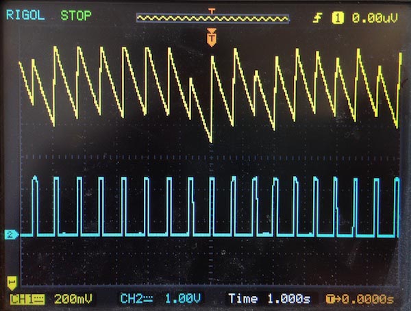
| Figure 2. | The time-dependent voltage output at nodes COMP (CH1) and Pulse (CH2). |
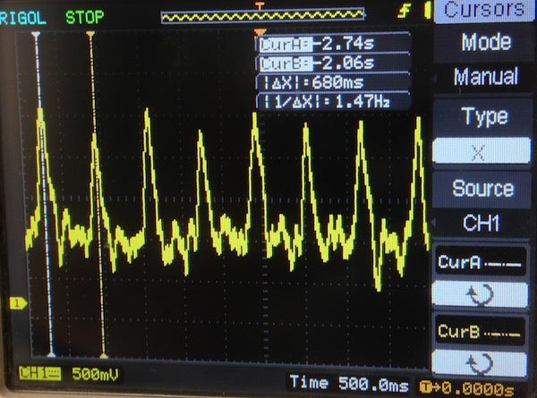
Figure 3. | The signal at node OUT. |
This article does not explain the pulse reading process, which can be done by any MCU with an ADC. The MCU is needed for controlling the LEDs, signal measurement, and signal conversion into the oxygen saturation. Calculation of oxygen saturation is possible even with the narrow bandpass filter used. After turning the red LED on, the signal is measured by the ADC. After two or three pulses, the infrared LED lights up for the same period as the red one. The MCU uses the equation
where the voltages are the peak-to-peak readings, and S represents the value of StO2 in a calibration table.
This work was supported by the Slovak Research and Development Agency under the contract no. APVV-0865-11 and contract no. APVV-0819-12 and VEGA 1/1177/12.
Video
