Chee Hua How
EDN
This Design Idea demonstrates a way to adjust the output voltage of a power supply, for OVP/UVP testing, margin-testing the load, voltage programmability, or any other reason.
The circuit in Figure 1 is capable of bidirectional trimming of a power supply’s output voltage by sourcing or sinking current into the feedback node. It can operate either manually with switches or digitally via three inputs: S1 (STEP), S2 (RESET), and S3 (U/D).
Every S1 rising edge increases or decreases VO by one step (about 95 mV in this design). S3 controls the adjustment direction (up/down), and S2 resets VO to nominal.
One shot U4B ensures:
- One incremental step per press (debounces S1).
- Sufficient waiting period for the UUT’s protection circuit to react.
The trim section comprising U5 & U6 features a voltage controlled current sink/source (VCCS). U3B & U3C shift up the VCCS’s reference point so that:
- It’s centered at the same level as VREF_PS. Thus, in neutral condition (e.g., upon reset), VW = ½VREF1 ≈ VREF2, ITRIM ≈ 0 & VO ≈ VO(NOMINAL).
- The circuit can use a single supply while still capable of sinking and sourcing current.
Difference amplifier U5 generates ITRIM to adjust VO’s magnitude, sourcing current into the VTRIM node to lower VO, or sinking current to raise VO. U6 is a G=1 instrumentation amp that feeds the sensed current back to U5.
The U1/U3C circuit generates two reference voltages, VREF1 and VREF2. VREF1 is a reference voltage for control signal VW. VREF2 matches the UUT’s 1.25 V reference voltage.
Equations (1), (2), and (3) can be used to configure this circuit for different VO settings:
 |
(1) |
 |
(2) |
 |
(3) |
The following example plugs Figure 1’s parameters into the equations:
|
|||||||
| Figure 1. | Circuit for bidirectional trimming of PSU output voltage. | ||||||
From (1) we have:
 |
(4) |
So for VO variations of ±25% (i.e., 30 V to 18 V), ITRIM is in the range of –26 µA to +25 µA.
VW is within 0 V-2.5 V. Putting this number into (2) gives R8 ≈ 48 kΩ.
From (3):
 |
(3a) |
 |
(3b) |
If R7 = 100 Ω then VA(VW = 0) ≈ 0 V and VA(VW = 2.5 V) ≈ 2.5 V.
Given the 128 steps of U2, resolutions for VW, ITRIM, and VO are 20 mV, 406 nA, and 95 mV respectively.
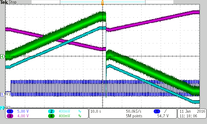
Figure 2 shows waveforms at a few key points. In the first phase, VO (Ch3) is decreasing linearly from nominal with every clock pulse until it saturates around 18 V. About half-way through, S2 is pressed to reset VO to nominal and S3 is closed. VO increases with each clock pulse to its upper limit of 29.5 V.
 |
|
| Figure 2. | Ch1:CLK; Ch2:VW; Ch3:VO; Ch4:V(R7+R8). |
Any mismatch between VREF2 and VREF_PS introduces an offset on ITRIM when U2’s wiper is centered which shifts VO from its nominal. This can be trimmed out if desired.
The circuit is powered by a 5 V source, with current consumption under 2 mA. In some applications, VO could be regulated and used for this.
