Matthew Grant, Linear Technology
Design Note 556
Introduction
The LT®3952 monolithic LED driver includes a 4 A, 60 V DMOS power switch, excellent for driving high current LEDs in buck mode. Among its many features is an input current sense amplifier, which can be leveraged to provide built-in LED voltage limiting in buck mode.
In buck mode, the anode of the LED string (LED+) is tied to the input voltage and the converter draws current from the cathode of the string (LED–). In the case of an open-circuit, a buck mode converter drives the nearly to GND (Figure 1). The total output voltage should be limited during this open-circuit fault condition.
 |
||
| Figure 1. | Buck Mode Topology. | |
One method of limiting voltage is to use an external PNP transistor as a level shifter. While this technique is adequate, a more elegant solution can be achieved by leveraging the internal resources of the LT3952.
The trick is to repurpose the input current sense amplifier on the IVINP/IVINN pins to act as a high side voltage regulator as shown in Figure 2.
 |
||
| Figure 2. | IVINP, IVINN as Output Voltage Limit | |
A resistor divider across the LED string allows the IVINP/IVINN pins to sense the output voltage. When the IVINP/IVINN voltage reaches 60 mV, the IVINCOMP output reaches 1.2 V and the output is limited. Tying IVINCOMP to FB, as shown in Figure 2, adds the benefits of output overvoltage protection and open LED protection.
For applications that utilize the PWM dimming function, a large value resistor from FB to GND prevents the FB pin from floating during PWM off-time.
Application Circuit
To test the design, an application circuit was built for a 40 W, 1 MHz buck mode LED driver. With the R1, R2 and R4 values shown, the voltage limit is roughly 22 V across the LED string.
 |
||
| Figure 3. | DC Measurement of LED– and LED– Limit. | |
Figure 3 shows measurement of the LED– voltage and the LED– open-circuit limit as VIN is swept from 0 V to 40 V using the circuit of Figure 4. The voltage limit tracks the input well over the full operating range.
 |
||
| Figure 4. | 3 A, 40 W, 1 MHz Buck Mode LED Driver with 22 V Output Limit. | |
Figure 5 compares the transient response for an open-circuit condition with and without the use of the output limit circuit: VIN = 36 V, ILED = 3 A, four series LEDs.
 |
||
| Figure 5. | Open-Circuit Fault with and without Limiter. | |
As you can see, an open-circuit fault without the limiter causes LED– to be pulled from its 23 V nominal value all the way to ground, resulting in nearly the full 36 V input potential from LED+ to LED–.
With the limiter, however, the output voltage is quickly limited to a more reasonable value. The connection of FB to IVINCOMP allows the fault to be indicated on the OPENLED pin.
 |
||
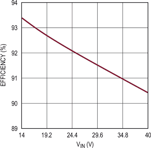
| Figure 6. | Efficiency vs Input Voltage. | |
The overall efficiency for this 40 W solution is greater than 92% at 24 V input voltage, and greater than 90% over the entire input voltage range of 14 V to 40 V (Figure 6). When using any output limiting technique, remember to leave some margin between the limit voltage and the normal operating voltage.
Conclusion
The LT3952 is a versatile, high performance platform for driving LEDs in multiple topologies. In addition to input and output current regulation, a host of features such as spread spectrum modulation, all internal PWM generator, and exceptional fault protection simplifies the design of advanced lighting solutions.
