Many projects need a good clean +12 V at a couple of amps (like a small PC or a laptop) and although a car has a 12 V battery the actual voltage available is everything from 9 V to 16 V and there is plenty of dirt in the powerline as well, to to run delicate electronics you need to clean up that power source before use.
Bob Blicks solution
It turned out that a clever dude called Bob Blick was here before me and solved the problem back in 2001, so I simply chose to ape him:) This next section contains the power supply information that I have mirrored here:
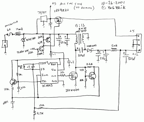
The power supply accepts 8 to 16 volts and produces 12 volts. The topology is SEPIC (single-ended primary inductance converter), the advantage being the ability to convert up or down with a minimum of parts and maximum efficiency. [...] the power supply is good for about 8 amps output and can power the system while starting the car.
SEPIC topology uses two inductors, but if you couple them your efficiency goes up. Don't go calling it a transformer, though :) I used an RM10 core, I don't know the exact material. It is wound in bifilar fashion. I used a bit of sticky label to add a gap between the two halves, and put a spot of epoxy in it to keep it from making noise [...]. RM is a generic classification for this type of ferrite core, and 10 is the size. If you can't find one, you can use a clamshell open core such as sold by RadioShack for reducing interference. It will look completely different but work just as well. Remember to add the sticky-label gap and glue it with epoxy.
The UC3843 chip is very common and made by many manufacturers using slightly different numbering systems. It comes in an 8 pin DIP package, but I only had 14 pin SOP versions so I used a DIP header and hacked it in. Three type of protection are incorporated in the design. First is a 6 amp Polyswitch fuse, it is self-resetting, and also protects against high temperatures. Next is an 18 volt surge absorber. Finally, the circuit has current limiting using a method I invented that limits based on saturation voltage of the main switching transistor. No current sense resistors are needed. The value of the big electrolytic capacitors is not critical but they must be rated for high frequencies.
My implementation
I couldn't get the surge suppressor or the polyswitch so I did without them, I'm not going to need a constant +5v and I want the on/off control a bit different so I've left that out as well for now.
The coils
The RM10 core and the two 12 uH coils weren't available either so I had to buy some cobber wire and some ferrite cores and do the coils myself.
I got a spool of 0.75 mm insulated cobberwire, a couple ferrite tourus'es and a clamshell open core and remembered that I hated making transformers back in school...
I took great care to hit 12 uH with the two coils but that was probably silly of me as I suspect that any value larger than that would have worked just as well.
For the clamshell I simply wound two windings at the same time and glued the core shut around a small piece of paper along with some locktite to keep it from singing (yes I tried it without the glue:)
Other differences
The guy at the parts store didn't have any high-frequency rated electrolytes so I got a stack of generic 1000 uF / 35 V radial ones, but they turned out to be fine, so I guess I was lucky.
For the NPN transistors I got BC547.
The schottky diode was replaced with an other one of slightly higher rating, but other than that they had all the stuff I needed.
In stead of adding a cooling plate (I didn't have any) I put it in a box with a small cpu fan from a long-time dead PC, that keeps everything chilly enough under real world loads.
Version 1 on protoboard
I've done a little testing to see how efficient it is, using my soldering iron as the load (1.24A@12V or 14.88 W) and the first time I powered it up input power was 1.88A @11.7 V or 21.996 W (68%), I then changed some of the caps and shortened some leads and that caused efficiency to go up quite a bit, 1.4A@11.7 V or 16.38 W (91%).
Shorting the output though my multimeter (10A max) shows that it quite happily pumps out 9-10A when fed 25V from my benchsupply (which maxes out at 5A, btw), you can hear the main core "strain" under the load and things start getting hot, but no smoke.
Important things to note for the next version are:
- Switch mode power supplies aren't that hard to build, go for it.
- It is very important to keep component leads and pcb traces short and fat, especially around the diode, transistor and the cils.
- Forget expensive magnetics and do the various magnetics yourself, it's easy, cheap and just as efficient as the "real" parts.
- Total cost (excluding prototyping PCB which you probably have and the spool of 0.75mm cobberwire): 172 DKK (26 USD), which is a lot cheaper than the commercial DC/DC converters.
Version 2 on PCB
After having completed the PSU on the prototyping board I wanted to see how small I could make it on a real PCB (single sided to keep it simple to make at home and cheap to make commerically) another limitation is that the maximum size of the PCB is 8x10cm (because I'm too cheap to pay for Eagle)
As it turns out I was able to make all of it fit onto an 5 x 8 cm pcb, which means that you can make a 10 x 16 cm pcb at Olimex for 21 USD, carrying 4 psu pcbs (that they will cut out for you), resulting in a price of 5.25 USD pr. PSU print, which is more than just dirt cheap.
Here are the Eagle files containing the schematics, PCB and a liberary that I had to make containing the T-MOS, UC3843 and the clamshell core: carpsu.eagle.v2.tar.gz [24K]
If you want a pdf, png or something else of the pcb because you don't have eagle and are too lazy to download and install it, drop me a line and I'll see what I can do.
I now have my 4 boards from Olimex and they look great, I screwed up a little and used too small drills for some of the holes and too small pads for the big caps, but the work they did was top-dollar.
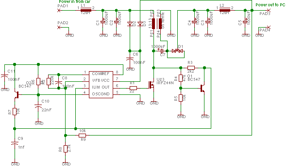
The output voltage is controlled by the R8/R9 voltage divider, the regulator tries to keep 2.5V at pin 2, so change to voltage divider to get the voltage you want, here I've used the E24 values that most (if not all) places carry, with a few exceptions it's possible to hit every voltage within a few mv:

The PCB for v2
| VT | E24 | |||
|---|---|---|---|---|
| VR | VE | R8 | R9 | |
| 5 | 5 | 0 | 1k8 | 1k8 |
| 5.2 | 5.2 | 0 | 3k6 | 3k9 |
| 6 | 5.96 | -40 | 1k3 | 1k8 |
| 7 | 7 | 0 | 1k | 1k8 |
| 8 | 8 | 0 | 1k | 2k2 |
| 9 | 9 | 0 | 1k5 | 3k9 |
| 10 | 10 | 0 | 1k | 3k |
| 11 | 11 | 0 | 1k5 | 5k1 |
| 12 | 11.97 | -29 | 2k4 | 9k1 |
| 13 | 12.96 | -39 | 4k3 | 18k |
| 14 | 14.03 | 29 | 3k9 | 18k |
| 15 | 15 | 0 | 1k5 | 7k5 |
| 16 | 16.04 | 39 | 2k4 | 13k |
| 17 | 17.01 | 10 | 6k2 | 36k |
| 18 | 18 | 0 | 1k | 6k2 |
| 19 | 19.16 | 160 | 1k5 | 10k |
| 20 | 20 | 0 | 1k3 | 9k1 |
Columns: VT: Target Voltage, VR: Resulting voltage, VE Error voltage in mv.
In case you are wondering, no I didn't do all of those values by hand, naturally I wrote a small piece of perl: resistorhit.pl [8.0K]
Version 3 on PCB
The next version will be much like the V 2, except for a few changes:
- Added a trimmer (R13) to the R8/R9 voltage divider so it's easy to get the exact voltage wanted and you don't have to change components to get another output voltage.
- Redone the PCB to fit the smaller low-imp caps that are about 2/3's the size of the original electrolytes I got a hold of (at Elfa, the stock number is 67-183-32 ).
- Added a 5V regulator to allow the GPS receiver (or headunit) to stay on, even when the computer is off.
- Added a low power on/off switch to the PSU so it's easy to control from a computer, the car should toggle the PSU on when the ignition is turned on, the computer should turn it off when pulling the off contact high while the car ignition wire is off. The +12 v car ignition signal should also be conditioned so it's suitable for a 5 v input on a CPU and made available, the standby current is around 30 mA, which I hope is low enough.

The PCB for v3
State Car [On] PC [Off] Output Running 1 X On Shutting down/off 0 0 No change, NOT OFF Turn off (short) 0 1 Off
The latest version of the eagle files are here: carpsu.eagle.v3.tar.gz [36K]

Voltage range
The values chosen for R8, R13 & R9 have been chosen to allow an output voltage range from 4.8 to 20.42 volt, this should be good enough if you have a steady hand
The range can be limited to 9.2-14.31 volt by using 1 k 8, 1k & 7 k 5 for R8, R13 & R9 respectively, making it easier to hit 12V accurately.
Shutdown logic
The logic that controls shutdown can be omitted should you want to keep the PSU running all the time, simply leave out R11, R12, R14, C13, D4, Q3 & IC2.
Constant 5 V
If you don't need the constant +5 V nor the shutdown logic you can ommit the C1 & IC1 as well.
Undervoltage run
The two diodes D2 and D3 are used to allow the converter to keep running even when the supply voltage is below 7.5V, which is the controllers shutdown point.
You might not want to keep the converter running at that low a voltage, because it could drain the battery, so you might want to disable this feature by leaving out D3 and jumping over D2.
