Ricardo Jiménez, Fernando D. Pacheco, and Blanca L. Rodríguez
Electronic Design
Measuring the low frequencies that are common in many real-world situations, such as biomedical or speedometer applications, is a challenge due to the long periods of the cycles. A medium-scale-integration (MSI) CMOS circuit (Fig. 1) can measure frequencies in the range of 0.33 to 3.00 Hz (equal to 20 to 180 RPM).
 |
||
| Figure 1. | The period-to-RPM converter circuit for signals of very low frequency makes extensive use of standard medium-scale ICs. |
|
The algorithm was designed to solve the equation
where T is the input-signal period and the "60" represents one minute. The circuit first measures the period with a 100-Hz time-base frequency, which holds the binary reading in a 74HC4040 counter, and then loops are made to determine how many times that period fits into the constant 6000.
The comparison technique is performed by a CD40103 8-bit synchronous countdown counter, which generates the first output pulse when the first clock arrives from NAND Gate A. This triggers the monostable IC6 (CD4538) that loads the down counter with the period T.
 |
||
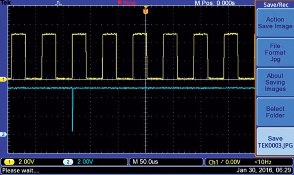
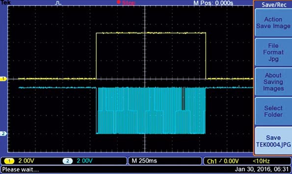
| Figure 2. | A frequency of 18 kHz is received by the down counter (CD40103), and the ZERO pulse is detected when the counter reaches zero. |
|
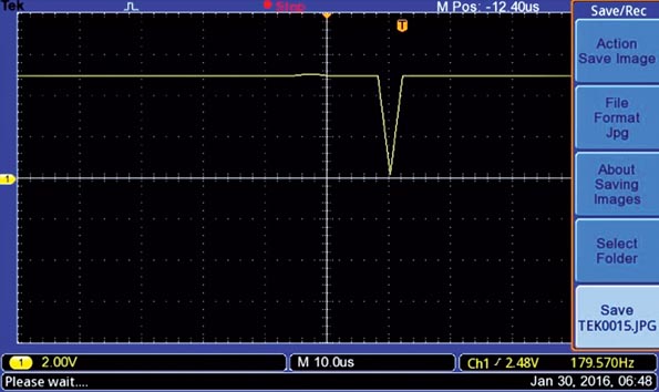
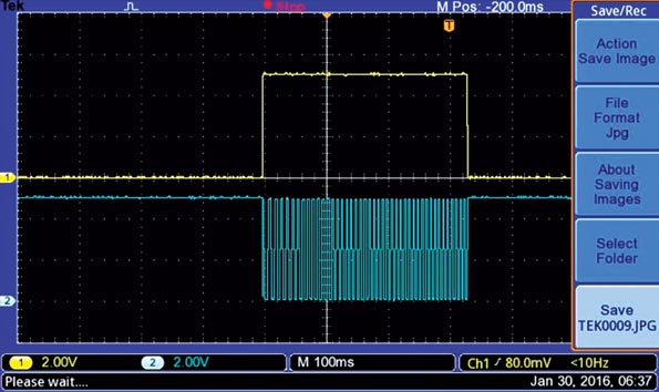
The 18-kHz frequency continues, and each time the counter reaches zero, the output pulses trigger monostable IC6 at the falling edge of that signal (Figs. 2 and 3). This signal is a feedback pulse that asynchronously presets IC2 (CD40103) for a new counting cycle. This process is repeated with a pulse train of 6000 pulses.
 |
||
| Figure 3. | The zero-detect pulse indication is provided by the down counter. | |
The pulse train is controlled by an 18-kHz logic oscillator and a frequency divider with a modulo equal to 6000. The frequency division is achieved with a MC14553 (IC4), CD4518 (IC5), and AND gate IC13 (CD4081).
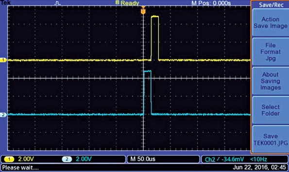
A master chip, the Johnson counter CD4017 (IC1), controls the entire process. In this counter, Q0 is the starting point. In Figure 4, when the first pulse arrives, Q1 goes to a logic-1 level to enable the 100-Hz logic oscillator. The input signal's period is then registered in IC2 (74HC4040).
 |
||
| Figure 4. | Q1 and the 100-Hz time-base pulse train are used to measure the period. | |
When the second pulse arrives, Q1 goes to a logic low and Q2 goes to a logic 1 (Fig. 5) to start the comparison process. An 18-kHz logic oscillator is used in this process. Once finished, the total number of pulses accumulated in BCD counters IC8 and IC9 (both CD4518s) will represent the period in pulses per minute (RPM).
 |
||
| Figure 5. | Q2 going to logic 1 starts the 18-kHz signal generated by Figure the second logic oscillator. |
|
In addition, when the comparison process is done, a pulse is sent by AND gate IC13 in the frequency divider. This resets both IC2, clearing the binary period reading, and IC1, making its output Q0 equal to 1. When Q0's output goes from low to high logic level, it drives two monostable circuits based on the CD4538 (IC7) to control the Latch and Reset functions of the BCD counters, as well as decoders that drive the LCD display (Fig. 6). The LCD phase signal is controlled by another 100-Hz logic oscillator, NAND gate D, made of one Schmitt-trigger NAND gate (CD4093).
 |
||
| Figure 6. | These Latch and Reset pulses were generated by the two half-monostables (IC7). |
|
If you need a higher range, augment the number of bits in the period counter CD4040, and add a second counter CD40103 in cascade. Due to the fact that the oscillator in NAND gate B has a startup time delay, adjust it to 120 Hz to compensate this delay and get true readings. A power-up reset-RC network (R7 and C7) assures that IC1 starts with Q0 = 1, and IC2 starts with a binary reading equal to zero.
The frequency equation for all of the logic oscillators used is:
 |
(1) |
and the startup time delay for each oscillator is given by:
 |
(2) |
where VP is the positive threshold voltage, VN is the negative threshold voltage, and VDD is the 5-V power supply.
The equation for all the monostables using the CD4538 is:
 |
(3) |
The power-up reset pulse is equal to:
 |
(4) |
All of the NAND gates used in this project are Schmitt triggers (CD4093BE) from Texas Instruments.
References:
Materials on the topic
- Datasheet Texas Instruments 74HC4040
- Datasheet Texas Instruments CD4017B
- Datasheet Texas Instruments CD4081B
- Datasheet Texas Instruments CD4093B
- Datasheet Texas Instruments CD4518B
- Datasheet ON Semiconductor CD4538BC
- Datasheet Texas Instruments CD4543B
- Datasheet Texas Instruments CD40103B
- Datasheet ON Semiconductor MC14553
