In this project we are building a JDM programmer that can handle PIC12, PIC16 and PIC18 family microcontrollers and some popular 24C family EEPROMs. The programmer also provides ICSP feature that allows In-Circuit Serial Programming. So if you desire, you will not have to carry your MCU each time when you reprogram it. The circuit is connected to the PC via serial port and no external power supply is needed. On the other hand, if you want to use it with a laptop that do not provide RS232 connection, using the circuit with a USB to RS232 converter may not give a proper result
Supported Devices
EEPROM: 24C01A, 24C02, 24C04, 24C08, 24C16, 24C32, 24C64/65, AT24C128, AT24C256, AT24C512, M24C128, M24C256, 24C515, PCF8572 or 8572 = 24C01, PCF8582 or 8582 = 24C02, PCF8592 or 8592 = 24C04, SDA2506, SDA2516, SDA2526, SDA2546, SDA2586, SDA3506, SDA3516, SDA3526, 4C016 == 24C01, GRS-003 == 24C02, GRN-004 == 24C04, GRN-008 == 24C04, GRX-006 == 24C04, GRX-007 == 24C04, KKZ06F == 24C01, BAW658049 == 24C02, BAW57452 == 24C02, M8571 == 24C02, X24C0
Microchip PIC: 12C508, 12C508A, 12C509, 12C509A, 12CE518, 12CE519,12C671, 12C672, 12CE673, 12CE674,12F629, 12F675, 16C433, 16C61, 16C62A, 16C62B, 16C63, 16C63A, 16C64A, 16C65A, 16C65B, 16C66, 16C67,16C71, 16C72, 16C72A, 16C73A, 16C73B, 16C74A, 16C74B, 16C76, 16C77,16F73, 16F74, 16F76, 16F77,16C84, 16F83, 16F84, 16F84A, 16C505,16C620, 16C620A, 16C621, 16C621A, 16C622, 16C622A, 16CE623, 16CE624, 16CE625, 16F627, 16F628, 16F628A, 16F630, 16F676, 16C710, 16C711, 16C712, 16C715, 16C716, 16C717, 16C745, 16C765, 16C770, 16C771, 16C773, 16C774, 16C781, 16C782, 16F818, 16F819, 16F870, 16F871, 16F872, 16F873, 16F874, 16F876, 16F877, 16F873A, 16F874A, 16F876A, 16F877A, 18F242, 18F248, 18F252, 18F258, 18F442, 18F448, 18F452, 18F458, 18F1320, 18F2330, 18F432
Building the Programmer
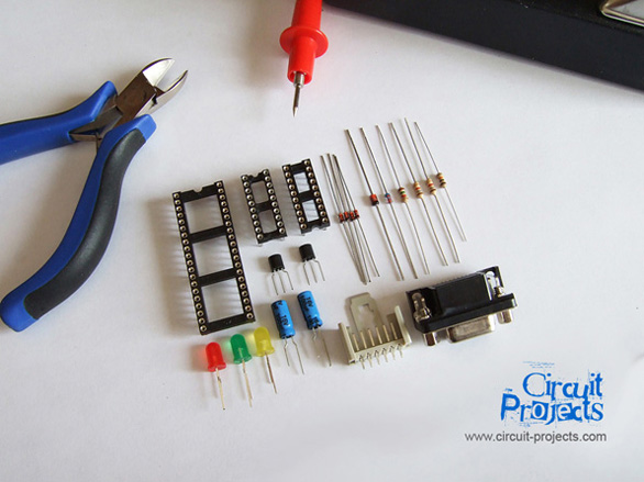
As you see the circuitry contains a few amount of components listed below.
Components List
{xtypo_code} T1, T2 : BC337 Transistor
D1, D4, D5, D6 : 1N4148 Diode
D3 : 6V2 Zener Diode
D2 : 5V1 Zener Diode
R3, R4 : 1K8 1/4W Resistor
R1 : 10K 1/4W Resistor
R2 : 1K5 1/4W Resistor
X1 : DB9 PCB Mount Female Connector
C1, C2 : 100uF 16V Electrolytic Capacitor
SV1 and SV4 : 80 Pin Machine Tooled IC Socket
SV2, SV3 : 20 Pin Machine Tooled IC Socket
SV5 (ICSP) : 6 Pin Header Connector
L1, L2, L3 : LED (L1: GREEN, L2: RED, L3: YELLOW) {/xtypo_code
Before printing the PCB layout, make sure you set the "Page Scaling" value to none in the printing options window. We used the ironing method to transfer the PCB layout. Be careful and don't forget to check the thin wires between the socket pins before etching.
Click here to download schematic and PCB layout files.

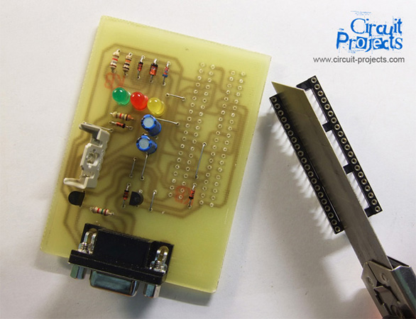
Assembling the components is straightforward. The only trick is shown in the photo. Before soldering the 80 pin socket, you must cut the plastic bridges between the sides. Another issue, don't forget to solder the diode (D6) and the jumper under the sockets first.
Here is the final. If you don't miss any short-circuits, you will see the red LED will bright up when you connect the programmer to the serial port. Now it is ready to use. You may use ICPROG and WinPIC to start programming your PICs or EEPROMs.
LED Indications; Yellow:Clock, Red:Power, Green:Program
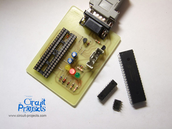
Placement is shown in the figure below.
Don't forget! Wrong placement may defect your IC, programmer or computer.
You may use a ZIF socket instead according to your needs.

