A Microchip PIC based USB sound card
INTRODUCTION
The idea for creating a USB sound card based on a PIC came from discussions of other people creating one on the Microchip USB forum. The hardware of the card is based on all Microchip products. The software uses a modified version of the Microchip USB framework which is interrupt driven instead of the traditional polling. The device is a USB composite device. The first device is an implementation of the USB Audio 1.0 interface and the other device is a custom interface based on a HID interface. The purpose of the custom interface is for programming the device serial number, upgrading the firmware, and in the future any other configuration that isn’t supported directly by USB Audio 1.0. In a previous version, WinHTTP was oringally used. After testing the card for awhile, I decided it's better to not require drivers for the card especially since the HID/WinUSB interface is rarely used.
The sound card runs at a sample rate of 48KHz, 32KHz or 24KHz selectable by the OS with 12 bits per sample. The quality approaches commercial grade as the sample rate is higher then CDs. 44.1KHz was not implemented due to the difficultly and additional processing overhead. The sample rates that were implemented are all a multiple of the 1ms USB frame meaning each frame sends the same amount of data. 44.1KHz requires the card to handle different amounts of data each frame requiring more advanced buffering and synchronization techniques and more processing power. Microsoft Windows automatically resamples the 44.1KHz audio found on CDs to 48KHz.
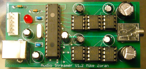
USB Audio Streamer V1.2
HARDWARE
Click for enlarge
Schematic for USB Audio Streamer V1.2
Eagle and PDF Versions of Schematic and Layout
The hardware for the sound card is based on the Microchip PIC18F2550 USB processor. The processor is clocked at 48MHz which is the maximum rate for this processor and is also a multiple of the audio sample rate. The microcontroller is connected via the SPI port to duel Microchip MCP4822 12bit D/A converters. Volume control is implemented by the Microchip MCP41010 variable res-- ders are controlled via SPI by the microcontroller via a dedicated bit-banged SPI port. The purpose of using a separate port is so that volume control can run inside the processor at a different priority level then sample output. The Microchip MCP6022 op-amp is used as an output driver.
The MCP6022 op-amp has an output drive capacity large enough to power a pair of cheap headphones without much distortion. The resistance of my headphones is approximately 25ohms. The op-amps are not powerful enough to drive speakers which are usually 8 or 4 ohms. The MCP41010 and MCP6022 can output near rail to rail voltage although some nonlinear effects can be heard if the volume is too loud or the signal is near the minimum or maximum. Since USB has a single rail 5V power supply, the sound card only uses a positive rail instead of a traditional duel rail system which is how standard 16bit PCM is encoded. As a result, the signal needs to be biased in software to 2.5V.
One terminal of the MCP41010 is connected to the signal for that channel and the other terminal is connected to the midpoint or bias voltage. Previous versions of this sound card connected the second terminal to GND. The advantage of connecting the terminal to the bias is that as the volume is changed, the signal grows or shrinks around the midpoint rather then shifting toward GND. The signal is kept as far away from the rails as possible.
SOFTWARE
The software for USB Audio Streamer is composed of several components. These are the audio card firmware, a C++ library that wraps HID and WinUSB, and a command line utility for flashing. I am giving out the source code as a learning tool for other people. I don’t care what you do with it but I am not responsible for any damage that might happen from using it. NOTE: Improper use of hardware or software may cause serious injury or death.:)
Source for USB Audio Streamer V1.2
I use Visual Studio 2005 Professional but I have heard that the project will build with Visual Studio Express. To build the project it is necessary to download the latest version of the WDK to get the headers and library files for HID and WinUSB. The default directories in Visual studio need to be modified to point to the directories of these resources in the WDK. If you use Visual Studio Express it's necessary to recreate all the project files and change the default calling convention to _stdcall.
| Directory | Function |
| inc | General Include Directory |
| boot | Boot Loader(Build first) |
| audiostream | Sound card firmware |
| usbdevprogramer | Programmer command line utility(Build last) |
Source Code Modules
A trick is used when building the sound card firmware since it is two separate projects that need to be merged together. Build the boot directory first, which is the code responsible for upgrading the firmware. Then build the sound card firmware itself. Before flashing, goto Configure/Settings/Program Loading and clear the option to clear program memory upon loading a new program. After the sound card firmware is build, goto file/import and import the hex file for the boot loader. The two projects will be merged together without any cutting and pasting. At this point, it is OK to flash the PIC. Note the bootloader is only necessary for flashing firmwares without a ICD/Pickit. When debugging actual card functionality, it's ok to leave out the bootloader. This Requires no modifications to the sounce or linker scripts. Simply don't merge the boot loader into the image
SOUND CARD FIRMWARE
The sound card firmware is based on a modified version of the Microchip USB framework. The framework has been collapsed into a single source file with callbacks between the framework and the main code. The framework( in my case it’s more of a library ) has been modified to use interrupts instead of the traditional polling method. Instead of calling USBDriverService in a loop, this function is called whenever the USB interrupt fires. The library is response for handling control requests on endpoint 0. The framework handles standard USB requests and the body code is responsible for handling class specific USB requests nonstandard requests. The body code is responsible for handling I/O on all other endpoints.
USB Audio Streamer is a composite device of a USB Audio 1.0 device and a custom HID interface. With USB Audio 1.0 all of the sample data is transferred through a separate endpoint then control requests. Control requests such as controlling volume is through endpoint 0(the control endpoint.) HID uses it’s own endpoint. Since each function of the card has a separate endpoint, each of the functions can be implemented at a different priority level without preemption problems. The PIC18F2550 has two interrupt priorities plus the main handler. This gives a total of three priorities. Since playing sound data is the most critical function it was given the highest priority. Next comes control endpoint requests which include the standard requests plus Audio 1.0 requests. Since these functions have relatively low timeouts, these were assigned low priority. HID functions are in the main body code because actions such as querying the firmware version, settings the serial number, or flashing the firmware are not time critical at all.
| Endpoint | Priority | Function |
| EP 2 | Interrupt(High) | Streams the audio data to the D/A converter |
| EP 0 | Interrupt(Low) | Control Endpoint function and Audio 1.0 requests |
| EP 1 | Main(Background) | Non standard functions |
Endpoints, priorities, and functions of firmware
CORE AUDIO
The low priority interrupt handler performs two functions. The first is to check the ISO endpoint through the SIE for data. If data is available the buffer is passed to the high priority interupt code and next buffer that makes up a cicular queue is returned to the SIE. The buffers are in the USB ram of the PIC so that the data is not copied between buffers. In Audio 1.0, the host always sends exactly the number of samples to fit in a frame which is 196, 128 or 96 bytes depending on the sample rate used.
The second function of the low priority interrupt handler is SOF(start of frame) processing. Upon receiving the SOF, the PIC changes the current play buffer to the next available buffer and starts timer 2 which is the sample clock. Timer 2 is always reset on the SOF to keep the sample clock synchronized when clock drift is present. If the SOF occurs before the current buffer is played, playback is changed to the next buffer. If the SOF occurs after the buffer is finished, the last sample is stretch. Since the clock drift is normally small, most of the time samples are not dropped. The time of the last sample is slightly different. This is not noticeable in the audio and is only barely noticeable when playing SIN waves.
The high priority interrupt is driven off timer 2 and has the function of formating the data in the format required by the converter and loading the D/A converter through the SPI port of the PIC. The samples are converted from 16 bits signed PCM to 12 bit unsigned and the endianess is swapped. After the buffer is finished, timer 2 is stopped so that if the clock of the card is ahead of the host, the last sample is stretched.
AUDIO 1.0 REQUESTS
All Audio 1.0 requests are handled via an extension of the USB framework. The low priority interrupt calls USBDriverService which services the control request. If the request is a standard USB request, the request is handled by the framework. If it isn't, the framework calls back into the main code which examines the request. If the request is recognized, the main code claims the request. If the request is a read request, the main body sets the address of a variable to sent to the host. If it's a write request, a variable is written to but the firmware sets a completion routine to be called at the end of the request.
The card only handles two types of requests which are volume control and sample rate selection. The current value of both of these is stored in a global variable. If the volume is adjusted, new values are loaded into the variable resistors. If the sampling rate is adjusted, a new period is loaded into PR2 for timer 2.
HID REQUESTS AND HOST SOFTWARE
The main body code polls endpoint 1 for custom requests in a loop. If the request is anything other then setting the serial or flashing the firmware, the request is handled in the main body code. Otherwise, the processor is put into a special programming mode. Upon entering this mode, all interrupts are disabled and the USB library is used in the traditional polling mode as program memory blocks are moved from the host. Flashing the microcontroller is reusable code that is used for multiple projects.
The host side consists of a C++ library that wraps HID and a command line C utility for configuring the card. These utilities are used for multiple projects and will be discussed in a separate topic.
TESTING 123...
The USB Audio Streamer uses instrumentation grade analog components so frequency response is not a major concern. The main concern is noise and signal accuracy due to nonlinear properties of the components, jitter, and that the sample clock can drift from the USB SOF clock.
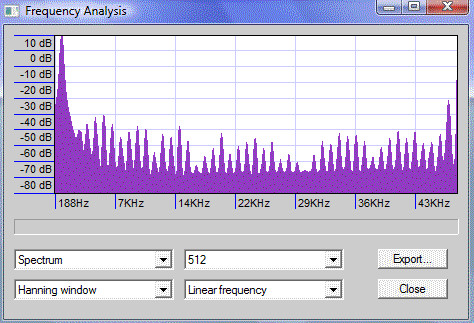
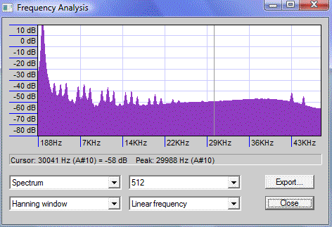
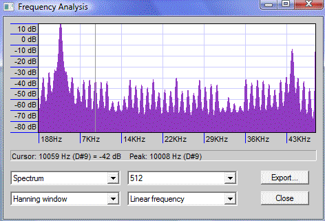
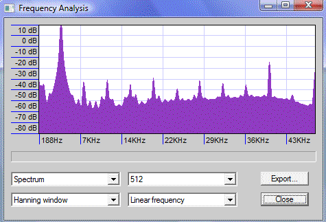
To measure the accuracy, I used Audicity to play 20 second sin tones of various frequencies and recorded the output on a Dell laptop with a built-in 24bit 96KHz Sigmatel sound card. The assumption is that the 24bit sound card is much better then the USB hardware. The output was recorded with Audicity and the spectrum of the signal plotted. The idea is that perfect hardware would have a single peak at the tone’s frequency and nothing elsewhere. The experiment was performed with both the USB Audio Streamer and a commercial 16 bit USB sound card the Turtle Beach Audio Advantage. In all cases, a 48KHz sample rate was used. In the follow graphs, the Audio Streamer is on the left and the Turtle Beach is on the right.
 Click for enlarge |
 Click for enlarge |
| 1KHz SIN | |
 Click for enlarge |
 Click for enlarge |
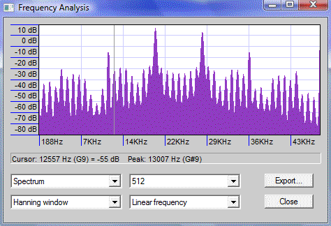
| 4KHz SIN | |
 Click for enlarge |
 Click for enlarge |
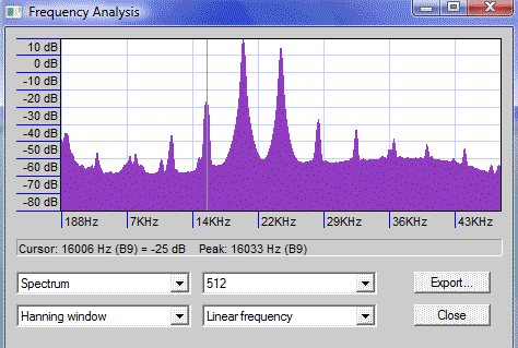
| 20KHz SIN | |
As can be seen, the accuracy of both devices decreases as the tone’s frequency is increased. Up to about 12KHz, both devices have approximately the same noise floor. At 12KHz though, the Audio Streamer’s performance begins to rapidly diminish. Both devices are isosynchronous adaptive, but apparently the Turtle Beach has better drift control algorithms. At 20KHz, even the Turtle Beach has noise of -40dB which is not that good. It seems that designing a high quality USB audio device is very difficult even for commercial developers.
| Tone Frequency | Audio Streamer | Turtle Beach |
| 1KHz | -50dB | -55dB |
| 2KHz | -50dB | -55dB |
| 4KHz | -45dB | -50dB |
| 8KHz | -40dB | -40dB |
| 12KHz | -35dB | -45dB |
| 16KHz | -30dB | -40dB |
| 20Hz | -25dB | -40dB |
