|
This application note is intended to be used as a development tool to speed up customers’ time to market.
Circuit Schematic
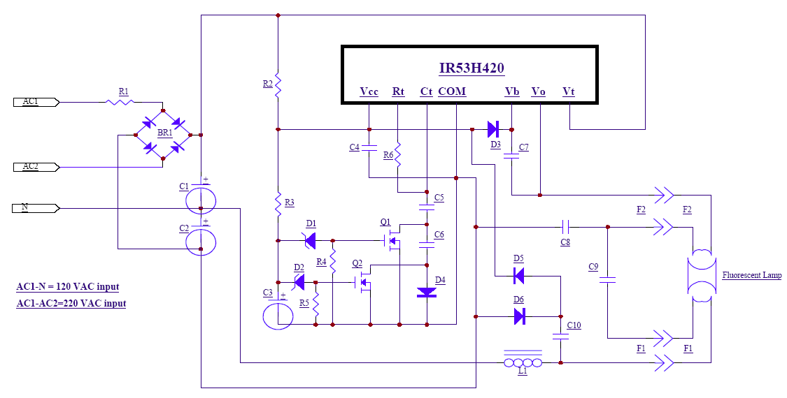
Functional Description
The circuit is centered around the IR53H420 Ballast Driver Hybrid which contains the IR2153 Ballast Driver IC and two 500 volt size 2 HEXFET’s in a half bridge configuration. With a 120 volt AC line input (AC1-N), the voltage is rectified and doubled to provide a bus voltage of approximately 300 volts. With a 220 volt AC line input (AC1-AC2), the voltage is rectified but not doubled and again provides a bus voltage of approximately 300 volts.The start up resistor R2 is sized such that it can supply enough current to start the oscillator in the IR53H420 but not enough to cause the shunt clamp to regulate and maintain constant oscillation. With this constraint the power dissipation in resistor R2 is low enough so that a 1/4 watt unit will suffice. A charge pump circuit, consisting of capacitor C10 and diodes D5 and D6, is used so that when the IR53H420 begins to oscillate, the charge pump circuit supplies the current to increase the voltage on Vcc to cause the shunt clamp to regulate. If the lamp is removed from the circuit there is no longer a path for the charge pump capacitor C10. This causes the voltage at Vcc of the IR53H420 to begin falling. When the voltage at Vcc of the IR53H420 falls below the negative undervoltage lockout threshold the oscillator stops
switching. At this point the voltage will begin to rise again and when the voltage reaches the positive undervoltage lockout threshold the IC again begins to oscillate. If there is no lamp installed in the circuit there will be no path for the charge pump circuit to supply current and the voltage at Vcc will again fall below the negative undervoltage lockout threshold. The circuit will continue this sequence indefinitely until the power is removed or a lamp is reinserted into the circuit. If a lamp is reinserted into the circuit, the lamp will light.
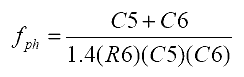
To provide long life and to insure soft-starting of the lamp, the cathodes must be pre-heated so that their hot resistance is approximately three to four times that of the cold resistance value. This is performed by using a three step start-up sequence; the three steps being three oscillator frequency settings. The oscillator is started at a frequency well above the resonant point of the LC circuit formed by inductor L1 and capacitor C9. This is done to insure that the initial voltage applied across the lamp is below the strike potential. The second frequency step, below step 1, was chosen to provide a current through the cathodes large enough to heat them in the pre-heat time while also maintaining the voltage across the lamp below the strike potential. The third step is to move the oscillator to the final running frequency. At this point the voltage across the lamp becomes large enough to strike the arc and the resonant point of the circuit shifts lower and the current in the lamp is limited by the inductor L1. The frequency shifting is accomplished by switching out different capacitors used to program the oscillator frequency. The capacitors are switched out by shorting them with MOSFET’s which are timed to turn on at different times. The pre-heat frequency is determined by the following formula:
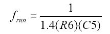
The pre-heat time is determined by an RC combination formed by R3 and C3 and the voltage of zener diode D1. When the voltage across C3 reaches the magnitude of the zener diode D1 + the turn-on threshold of Q1, capacitor C6 is shorted out and the frequency shifts to the final running frequency. The final running frequency is given by the formula:
The final component values, shown in Bill of Materials, were chosen to operate a 13 watt compact fluorescent lamp with a cathode resistance at cold of 4 ohms. If a lamp is used which has a different cathode resistance the component values for the pre-heat frequency selection will need to be changed. The ballast circuit was operated at various temperatures from 25 degrees C to 105 degrees C with little or no change in the operating characteristics.
Bill of Materials
|
REF. DES. |
DESCR. |
QTY |
P/N |
MFG |
|
U1 |
IC |
1 |
IR53H420 |
IR |
|
Q1, Q2 |
MOSFET |
2 |
IRLML2402 |
IR |
|
BR1 |
BRIDGE RECTIFIER |
1 |
DF10S |
IR |
|
C1, C2 |
10µF/250V |
2 |
ECE-A2EU100W |
PANASONIC |
|
C3 |
1µF/50V |
1 |
ECE-A50Z1 |
PANASONIC |
|
C4 |
2.2µF/50V |
1 |
ECE-A50Z2R2 |
PANASONIC |
|
C5 |
1000pF SMT1206 |
1 |
ECU-U1H102KBM |
PANASONIC |
|
C6 |
3300pF SMT1206 |
1 |
ECU-U1H332KBM |
PANASONIC |
|
C7 |
.1µF/50V SMT1206 |
1 |
ECU-V1H104KBW |
PANASONIC |
|
C8, C10 |
470pF/1KV SMT1812 |
1 |
102S43N471KV4E |
JOHANSON DIELECTRIC |
|
C9 |
.01µF/630V |
1 |
MKP10 |
WIMA |
|
R1 |
1.0Ω,1/2W |
1 |
1.0H-ND |
YAGEO |
|
R2 |
240KΩ, 1/4W |
1 |
240KQBK-ND |
YAGEO |
|
R3,R4 |
1MΩ,1/8W SMT1206 |
1 |
ERJ-8GEY105 |
PANASONIC |
|
R5 |
2.2MΩ,1/8W SMT1206 |
1 |
ERJ-8GEY225 |
PANASONIC |
|
R6 |
20KΩ, 1/8W SMT1206 |
1 |
ERJ-8GEYJ203 |
PANASONIC |
|
D1 |
7.5V Zener, SMT SOD123 |
1 |
BZT52-C7V5DICT-ND |
DIODES INC |
|
D2 |
3.9V Zener, SMT SOD123 |
1 |
BZT52-C3V9DICT-ND |
DIODES INC |
|
D3 |
Diode, 400V Fast |
1 |
10BF40 |
IR |
|
D4, D5, D6 |
Diode, SMT DL35 |
1 |
1N4148 |
DIODES INC |
|
L1* |
2.5mH |
1 |
9677142009 |
FAIR-RITE |
 |
 |
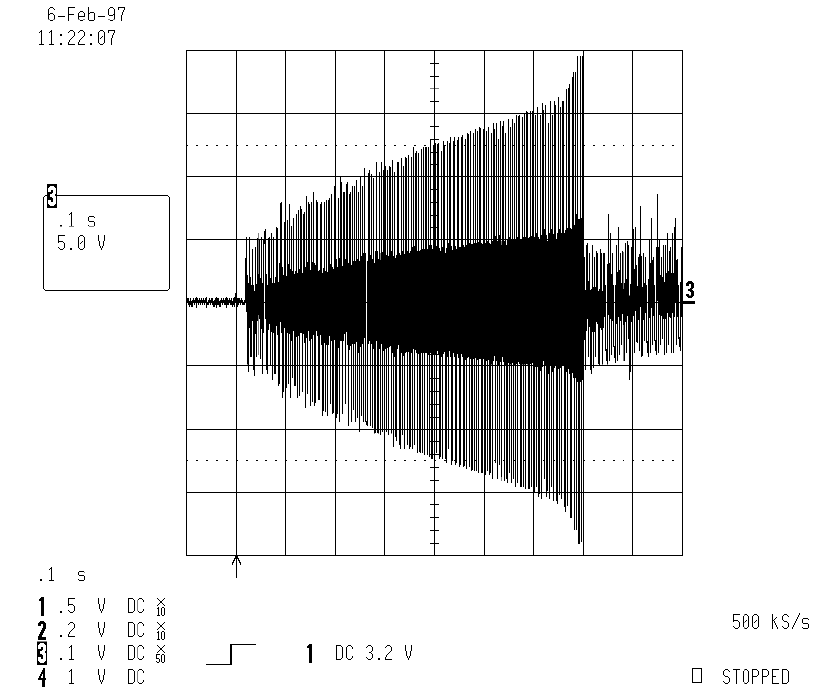
| Figure 1: Cathode Voltage (Start - Preheat - Running). This figure depicts the increase in cathode resistance during the preheat phase prior to ignition. |
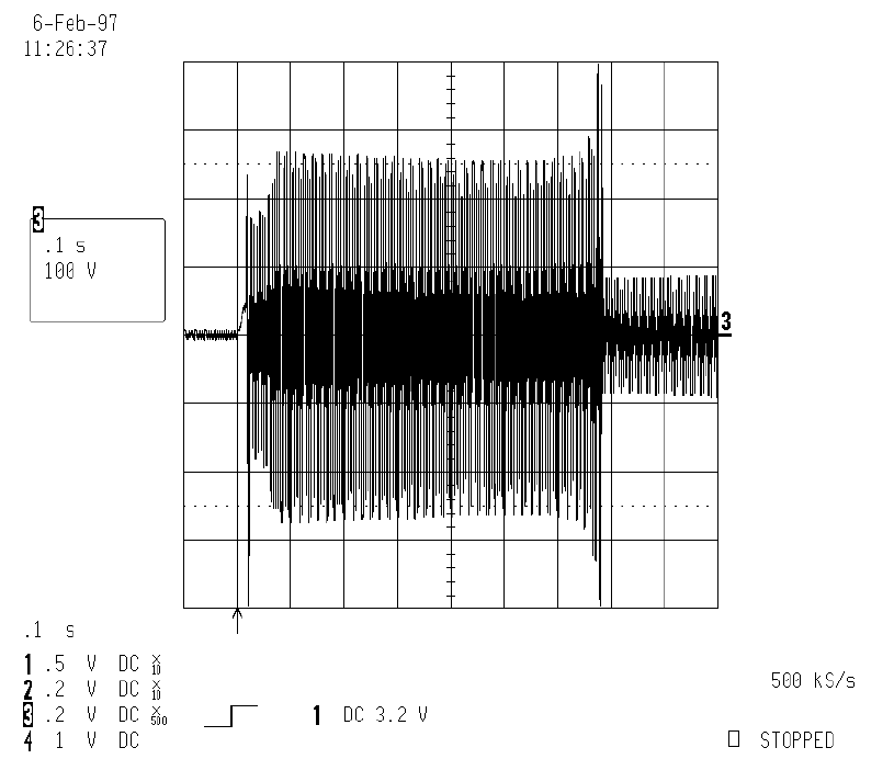
Figure 2: Cathode Current (Start - Preheat - Running) (500mA/div). This figure depicts the almost constant current in the cathodes which decreases after ignition. |
 |
 |
| Figure 3: Lamp Voltage (Start - Preheat - Running). This figure depicts the magnitude of the lamp voltage during preheat, at ignition and during running. |
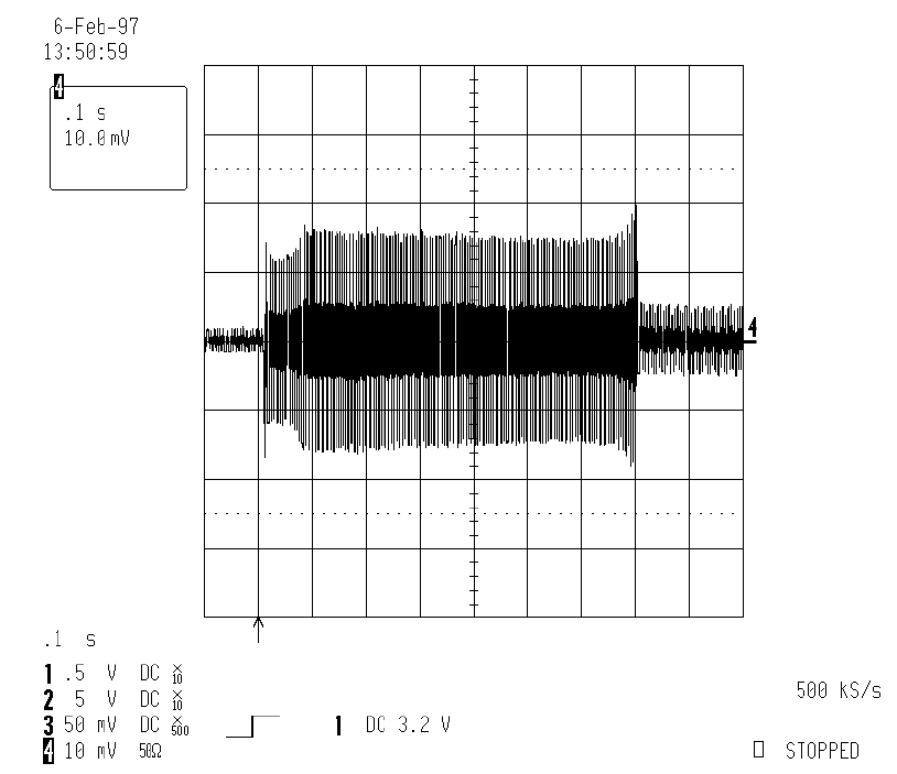
Figure 4: Lamp Current (Start - Preheat - Running) (200mA/div). This figure depicts the lamp current during preheat and after ignition. |
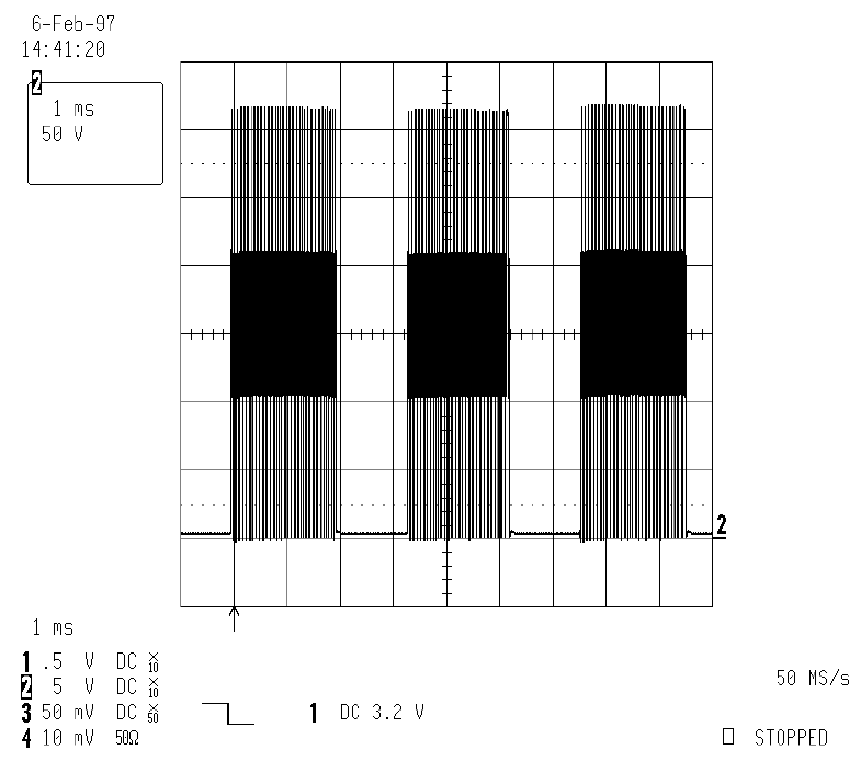 |
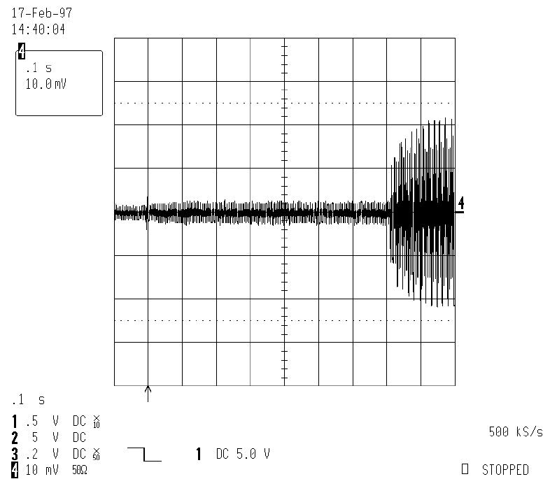
| Figure 5: “Vout” with Lamp Removed (burst mode). This figure depicts the “lamp out” condition with the output of the half-bridge in intermittent mode of operation. |
