How many times have you wished that you recorder your recent telephone conversation? I have, many many times. So I finally decided to make this happen by using PC and a piece of hardware (powered from USB) to record audio from phone line to MP3 format. I wanted this thing to work automatically, to start recording when any of phones in house is picked-up (line occupied) and stop recording when all phones are hung-up (line free).
How does it work?
The hardware-part consists of:
- audio pickup circuit
- phone line status monitor
- microcontroller Microchip PIC16F84 to send the phone-line state to PC using USB (serial<->usb)
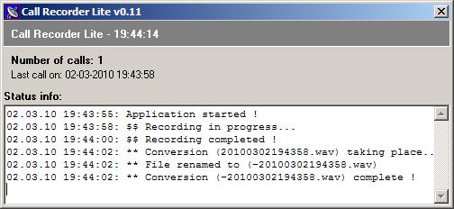
The software:
- receiving the phone-line state via USB and managing the recording to WAV
- after conversation is finished, converts WAV to MP3 using Lame library
Phone line status monitor circuit
This circuit is basically measuring voltage on the phone-line, which is is above 15 Volts (around 50) when on-hook. When any of the phones is picked-up the voltage drops below 15 Volts. This property is used to detect whether the phone line is in-use or not. The circuit is actually taken from this address and altered a bit.
Audio pickup from telephone line
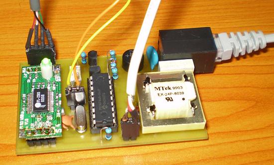
In this simple part a transformer from an old PC modem i used. There are also 2x1N4148 diodes to limit the output voltage of the transformer to ~0.6V, a resistor and a capacitor. The important part is this capacitor which ensures that phone-line is never occupied by the circuit.
Microcontroller to send data to PC
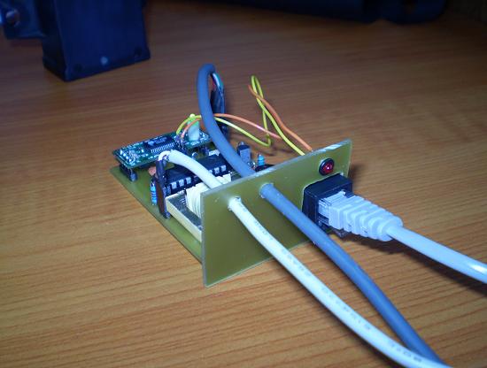
Microcontroller is checking the phone line status every 0.2 seconds with a help of monitor circuit above. If the optocoupler is "closed" for more than 0.15 seconds it means that the phone line is occupied and it starts to send letter "R" (Rec) to PC application. In other case it sends "S" (Stop). This data is received by the PC where the application starts audio recording (R) or stops (S). Since the microcontroller uses serial communication to send the data, PL-2303 circuit is used to translate those signals to USB. (An entire PCB converter is used in this application, as it can be seen in the picture.) Much better way of doing this is would be with V-USB library (see these simple projects). That way we could use only one Atmel chip instead of these two (PIC + PL-2303).
Components are used in this project
|
Обозначение |
Значение |
|
VR1 |
Varistor - optional |
|
С1 |
0.1 - 2uF, 400V |
|
С2 |
22pF |
|
С3 |
22pF |
|
BR1 |
Bridge rectifier for >= 200V, or simply 4 x 1N4004...7 diodes |
|
D1 |
1N4148 |
|
D2 |
1N4148 |
|
ZD |
1N4744 (or any other 15-27V Zener diode) |
|
R1 |
680 |
|
R2 |
4M7 |
|
R3 |
10М |
|
R4 |
10М |
|
R5 |
10k – 100 k (experiment for different OPT1) |
|
R6 |
220 |
|
R7 |
10k |
|
T1 |
|
|
T2 |
BC546 / BC547 |
|
OPT1 |
NEC2502 or any similar! (adjust R5 accordingly) |
|
PIC |
PIC16F84(A) |
|
LED |
LED red |
|
XT1 |
4 MHz |
|
PL-2303 |
PL-2303 or other USB<->Serial converter |
Schematic, PCB, soutce code and hex-file for PIC16F84, Windows application
