Matt Meerian
(Below is a video of some of the features of the clock. Portions of the video are a little blurry, but that is due to the web cam and not the display of the clock)
Launch in external player
Why build the electronics of a clock? Well, there are times when I use an electronic device and wish it would have some feature that is not included. (And I also like to clear out the cobwebs in my brain put there by network television) When engineering and marketing get together to design an alarm clock in a business, they put in features that only the majority of people would use. For those of us that would like to see a special “feature” (or features) in a device, our only choice is to do it ourselves. For many years now, I have turned the face of my alarm clock when I go to bed because the eerie green light from the LED segments are too bright when I am trying to sleep. This dilemma has led to my “Graphical Alarm Clock” project.
The key ingredients to this “recipe for a clock” are a graphical LCD from Optrex (2.8 inch, 128×64 pixel, blue and white display), a photocell and an ATmega32 microcontroller from Atmel.
Operation:
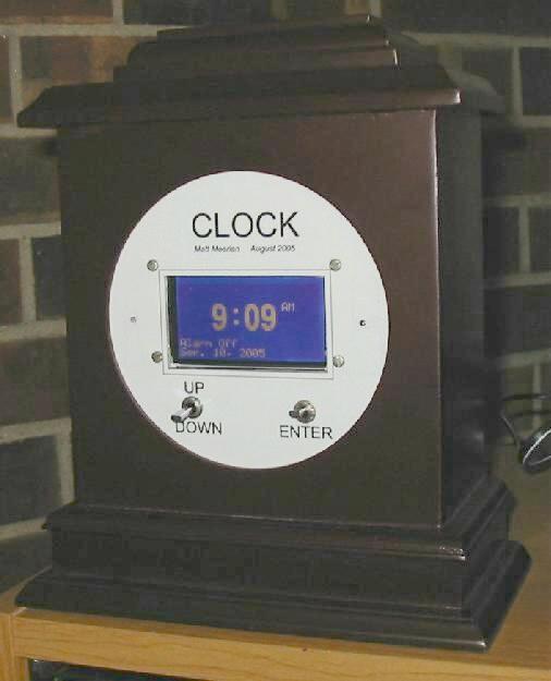
The clock has a very simple user interface. The button on the right, “enter” is used to access the menu. Once in the menu, the user can select several different options by using the up/down switch on the left. When the user is on the desired operation, the enter button is used to select the operation. For instance, say we want to set the time. From the main clock display; press the enter button to enter the menu, move down one line, and press enter and then you are in the “set the Time” screen. The hour is blinking and the up and down button will change the hour. Pressing the enter will move to the minute and then the up/down will change the minute. Anyway, you get the idea. The month, day, and year are set the same way in the screen. Once the year is set, press enter, and you are taken back to the main menu. The cool features of the project are the “Backlight time” and “Photo Trigger Value.” The backlight time is the on/off time of the backlight. Usually the values are set to 10:00pm for the backlight to go off and 7:00am for the backlight to come on. The “Photo Trigger Value” is the light intensity level that the backlight will come on. For instance, if you get up at 3:00am and turn on a light to go to bathroom, the photocell will sense this and turn on the backlight of the clock. When you turn off the room light, the photocell will again sense this and turn off the backlight.
Exterior
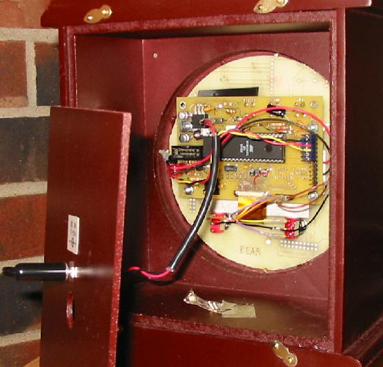
The microcontroller board and display mount to the “scrap” front panel circuit board. (The “Scrap” circuit board is used for mounting the switches, photocell, alarm buzzer, and microcontroller board; it was easier to cut a scrap circuit board than to cut 0.062” aluminum.) A front panel lexan (with button labels and a title) was made with AutoCAD light ’97. It is an old program, but works great for front panel lexans. Double-sided sticky tape was used to attach the lexan to the “scrap” circuit board front panel. The two buttons on the front panel are toggle switches. Push buttons on the front would have resulted in the clock being pushed backwards when the user would press them. The toggle switches have an up/down motion, so the clock does not move when actuated. The hole on the left side of the Optrex display is the alarm buzzer. The hole on the right side of the display is the photocell. The enclosure is a wooden clock from the dollar store. The original clock guts were tossed in the trash and the “scrap” circuit board was epoxied into the enclosure. The power for the clock comes from a 9V “wall wart” power supply. The power comes in through a 2.5mm barrel plug in the back of the clock.
To be continued
