Matt Meerian
The main idea behind this project was to make Christmas gifts for friends and family that would be somewhat useful. A clock was chosen simply because it is something that everyone uses and it would be relatively easy to complete. Also, a big limiting factor was the project was started only 40 days before Christmas.
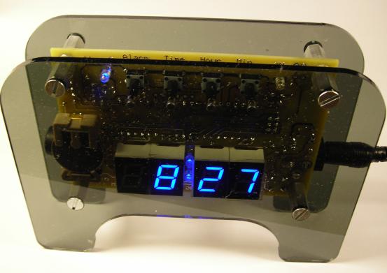
Image 1: The fully assembled clock
Operation and Basic Parts:
As you can see from the picture, the circuit board is sandwiched between two sheets of transparent gray 1/8" (3.175mm) acrylic. The sides of the enclosure are open and the 2.1mm DC power jack comes in from the right. The alarm buzzer is mostly hidden on the left side of the circuit board. There are four, blue, 3mm LED's used on the circuit board. Two are used between the hour and minute 7-segment LED' modules. The third one is used to indicate the alarm is on or off. The fourth 3mm LED is used to denote either it is AM or PM. The clock uses a small lithium battery to keep the current time if power is lost. The alarm time and state are saved in EEPROM and restored after a power outage.
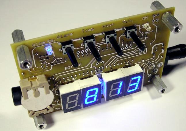
Image 2: The bottom of the circuit board
Without the smoked gray acrylic, you can see the push buttons much better. The four pushbuttons are: Alarm, Time, Hour, and minute. As you can see from the image above, the buttons have the labels over them. (the AM and Alarm LED's also have labels over them) To set the alarm, you push and hold the alarm button, then press the hour and minute buttons to set the correct alarm time. Likewise, press and hold the time button and then use the hour and minute button to adjust the time. Pressing the alarm button turns the alarm on/off. When the alarm goes off, any of the four buttons can turn off the alarm.
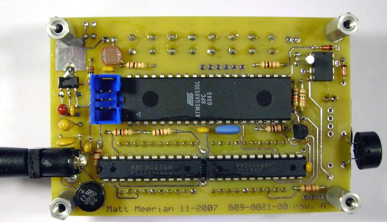
Image 3: The top of the circuit board
The large IC in the middle of the circuit board is the Atmel Atmega8535. The microcontroller is running at 4MHz and is in circuit programmed through the blue 6 pin header to the left of the Atmega8535. The Real Time Clock is the 8 pin DIP in the upper right of the circuit board. The two main LED display drivers are near the bottom of the above image. The piezo element for the alarm is the black cylinder on on the right and of course the power comes in through the DC power jack on the left. The photocell used to detect the ambient light level is right above the blue 6 pin header.
Schematic:
The power comes in at the top left of the schematic. A bridge rectifier is used so the polarity of the input signal doesn't matter. A small SOT223 package, 5V regulator is used to provide regulated voltage the Atmega8535, RTC, and the LED display drivers. The Real Time Clock data is comes in from the PCF8563P. This IC has a 32.768 crystal to keep time and a uses a 3V CR2032 lithium battery when powered down. SW1 - SW4 are the four pushbuttons for user input. The MBI5027 constant current display drivers (24 pin DIP) from Macroblock can be a little hard to find. They use power directly from the wall transform to turn on the 7 segment LED's. This way, the 5V regulator doesn't get hot from supplying the power to the LED's. (An alternate to the MBI5027 would be the A6276 from Allegro MicroSystems Inc. It's a little easier to find, Newark has the part in stock. (December 2007)).
PCB layout:
The PCB layout file is located at the bottom of the page. The Express PCB mini board service was used. With this order, they had the circuit boards here much quicker than in past orders. When assembling the boards, I had to be sure to the put the two colon 3mm LED's in first, then the MBI5027 display drivers, and then the 7 segment LED's. When parts go on both sides of the board, you have to really watch what order is used to solder down the components.
Figure 1: A screen capture from the Express PCB software
Partial Hardware Bill of Material: (hard to find parts)
- An 82 degree, 3 flute, countersink was used on the panel for the flat head screws. McMaster-Carr #3013A22
- Eight flat head machine screws were used on the front and rear panel. 6-32, 1/4" long, McMaster-Carr #90275A106
- Four female, threaded hex standoffs were used to hold the circuit board, 6-32, 1/2" long, McMaster-Carr #91780A127
- The 12.2mm, piezo speaker is from digikey: 445-2525-1-ND
- The holder for coin cell is from digikey: BA2032-ND
- The 3mm, 468nm, blue LED's are digikey: 754-1248-ND
- The 6mm, 160 gram force, pushbuttons are from digikey: 450-1643-ND
- The 7-segment LED's were purchased for about $20 for 20 units on E-bay. No part number, but digikey has equivalents.
Front and Rear Panel:
The front and rear panel was drawn in SolidWorks 99. (See the "Front and Rear Panel" link at the bottom of the page. Several different shapes were looked and the most conservative design was the one I ended up using. SolidWorks 99 is a 3D modeling program and the circuit board, front, and rear panel was partially built up to show how things would fit together. The order for 5 of the front and rear panels was from http://www.customlasercutting.com/. This was my first order from them. It took them about a week to respond to initial request for a quote, but once the quote was received, they manufactured the panels quickly and shipped them. For five front and rear panels (10 pieces total) it was $42 (USD) and that included shipping. The good news is they quickly loose the "burnt plastic smell" after the package is opened.
Software:
The software was written in AVR Studio, using the AVRGCC compiler. Timer 0 is used to update the display and act as timebase for a 20ms "tock" used in the main loop. Timer 1 is used only to make the alarm sound at about 1kHz. There are only 3 states of operation: Show the time, Set the time, and Set the alarm time. The software is commented, so it should be strait forward to understand. The twi.c and twi.h file was left out of the source code. (these files are used to get and set the time from the Real Time Clock) I used a non-freeware library, so if you want to compile the source code, you have to make your own library file to talk to the PCF8563P.
Summary:
The clock was started on November 13, 2007 and finished on December 20, 2007. Ahhhhh, on to the next project.
Downloads:
- Blue Clock "C" Source Code (WINAVR version 3.4.1) (zipped)
- Blue Clock PCB Layout (in ExpressPCB version 6.1.2) (zipped)
- ExpressPCB Viewer/Editor here
- Front and Rear Panel (PDF format)
As always, use at your own risk!
*All rights reserved, all wrongs deserved*
