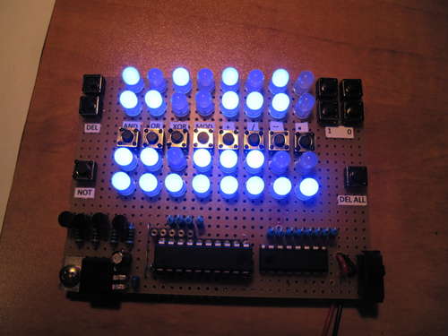
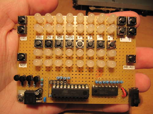
You can't calculate binary values "as is" on most handheld calculators and using the windows one is just a pain, so i decided to make my very own (binary only) calculator. This calculator supports all the basic functions like : NOT,OR,AND,XOR, addition,subtraction,multiplication,division and modulo.
So join me as we are going to enter the world of ones and zeros and play with some LEDs and switches along the way!
Parts List
Like any electronics project you will need to get some basic tools like:
a soldering iron, some solder wire, a cutter, a needle nosed plier,some wire, wire striper, and some desoldering tools fro fixing mistakes along the way.
The parts for the calculator:
- 32 LEDs.
- 8 resistors( The value is determent by the type of LEDs, in my case 91 ohm).
- 74HC595 shift register.
- 9 1KOhm resistors.
- 4 2N4401 transistors.
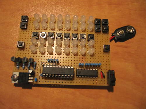
- A Perfboard.
- ATtiny2313 from Atmel.
- 16 tact switches with 4 pins.
- some pin headers.
- A programmer for the micro.
- 9V battery holder.
- A slide switch.
- 7805 voltage regulator
- 100nF cap
- 10uF cap
How to Control 16 inputs and 32 outouts?
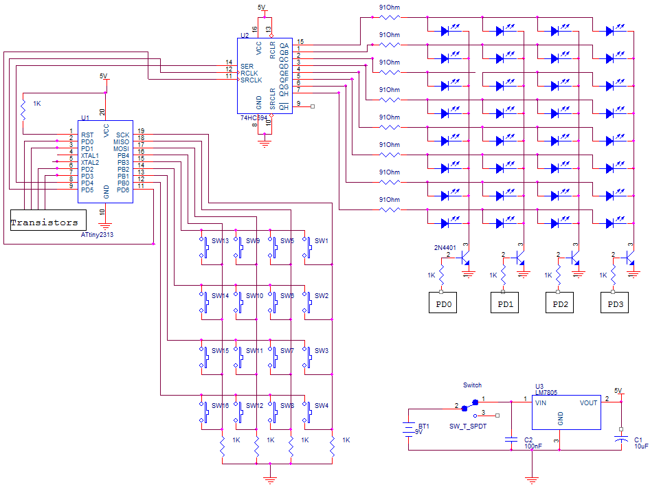
I had an ATtiny2313 micro in my parts bin and I wanted to use it for something, the thing is that it only has 17 outputs minus 2 if you use a crystal, and to control so many outputs and inputs I had to use some tricks to get around using just 15.
The first trick is multiplexing the the LEDs and arranging it in a matrix form, we connect the LEDs in a grid of 8×4 so now we need 12 outputs and not 32 but thats still a lot and we will need to find a way to get that number smaller. So I used a 74HC595 shift register which needs only 3 pins from the micro and gives you 8 outputs, the 74HC595 controls the columns and the micro scans the rows with the help of 4 transistors, and now we can control 32 LEDs with only 7 pins.
The second trick is to multiplex the switches as well and arrange them in a 4×4 matrix, and now we only need 8 pins to read the switches and not 16.
All the logic operations are being made in software so if you know your C you could use any micro-controller with 15 I/Os or more and adapt my code to work with it.
Schematics
As always the only thing I left out in the schematics are the resistor values which limit the current to the LEDs, this is a thing every one does by himself.You can use a special site to calculate the resistor value like this one. Or do it yourself with the help of a simple equation (Vin-Vled)/(Iled).
Soldering Tips
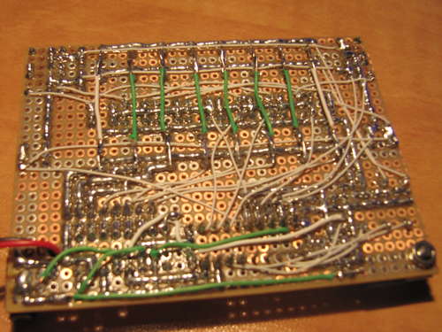
The two tricky parts in this project is soldering the LEDs and the switches and thats because the connect in a matrix formation.
Soldering the LEDs are a lot easier and the way you need to do this is to bend the positive lead of the LED down towards the other ones and make a column, and snip off the leads you didn't use and make the connections as low as you can get, and you do this to all of the positive leads.
Now the negative leads are connected in a column and thats make soldering tricky because the positive rows are in the way, so you will need to make a 90 degrees bend with the negative lead and make a bridge over the positive row to the next negative lead, and so on to the next LEDs.
Now because there are switches between the LEDs rows you will need to make 8 jumpers for connecting the 8 columns, the jumpers can be made from simple wire with isolation or you can use magnet wire.
The switches gives the biggest headache because they aren't soldered in a grid and thats makes it hard to connect them in a matrix form.I used a method called wire wrapping which uses a very thin isolate wire to connect points on the board. I have also added a wiring digram of the switches.
The controller circuit is simple and every one chooses how to make it so the only words of advise I will give is to bolt down the voltage regulator to the board to protect it from vibration and shock that can cause it to fall off, make a little hole in the board for the battery wire and by so creating a strain relief and the last thing is to add some pin headers for programming the micro unless you want to take out the micro every time you wish to program it.
It's Programing Time
This is the last thing to do, to make the calculator run.
I wrote a basic program for it so it can calculate all the needed things, I have the description of what every button does in the picture.
People who know C can easily adapt my code to make it run on the arduino or other platforms it's just a matter of changing the output and input commands. The code is fully documented so you can understand what each line does.
If you're going to use an ATtinty2313 I have added an HEX file as well to save some time. And if your going to use the HEX file remember to set the fuses to use the internal oscillator on 8Mhz.
I used the USBasp to program my micro but you can use any program you like or have at home.
Downloads
