Magirescu Iulian
Introduction
In the first place, a relay is like a switch to a coil assembly. This switch is activated when electricity is applied to the coil. With a common relay, the electricity must be continuously applied to the coil to maintain the contacts, but the impulse relay "remembers" and only requires a momentary application of electricity. Stated differently, apply pulse of electricity to the coil to turn on the relay contacts, apply another pulse of electricity to turn off the relay contacts.
So, impulse relay use it for to turn on a lamp with pushbuttons and not toggle switches. What is really neat is connecting several momentary pushbuttons in parallel and placing them in different locations. I can turn on the lamp in one room, and turn it off from a different room, because it was the relay that was providing electricity to the lamp, not the switch.
Description
A digital impulse relay is a electronic circuit that mimics perfect the all functions of a impulse relay with ratchet mechanism: the first press to the button turns the relay on and the second press turns it off, and relay in the circuit operating room illuminates. Particularity of this circuit is that it can be used in a centralized system for home automation. Another advantage is lower price compared with that of the impulse relay with ratchet mechanism. Digital impulse relay is immune to electrical noise, connection between buttons and circuit can be achieved with unshielded cable and any length.
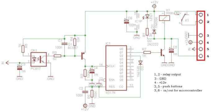
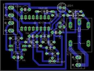
Schematic
This circuit is operating the room illuminates. The basic component of the circuit is a IC1 (CD4017). Push buttons room are connected by normally wired to the circuit. All circuit is separately by optocoupler, which means that the circuit is immune to electrical noise that can come on cable that connects with push buttons.
First any button push put to GND the optocoupler IN. The output signal from optocoupler is amplified by transistor Q1 (BC557) together by C1, R3, R4 circuit. The amplified signal is attack to clock pin 14 of decade counter IC1 (CD4017), the counter advances by 1, pin 2 goes high and relay is ON. Transistor Q2 (2N2222) connected to pin 2 of IC1 drives 12V relay. Diode 1N4004 (D1) acts as a freewheeling diode. LED1 indicate the ON/OFF status.
Second any button press, the IC1 advances by 1, pin 2 goes low, relay is OFF, and pin 4 goes high. If we connect by diode D2, pin 4 to Reset pin of CD4017, the counter is going back to the initial condition, and is ready to get another button press, to turn the relay ON.
The C2 - R6 component keep the Reset pin to +12V, when the circuit is powering, until the C2 loaded at 12V.
From transistor Q2 colector is IN/OUT for use in to microcontroller system (GSM remote control, WEB control, etc.). When use as IN, microcontroller system can put to GND Q2 colector, and relay is ON. Or the colector is use as OUT, signal obtained say the microcontroller system, if the relay is ON or OFF.
The power supply for the circuit is DC 12V. In standby, when relay is OFF, digital impulse relay consume 0V. Otherwise, when relay is ON, consume depend of 12V relay current.
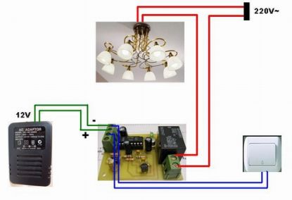
Installation
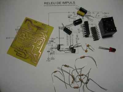
Parts List
|
Part |
Description |
|
IC1 |
CD4017 |
|
Q1 |
BC557 |
|
Q2 |
2N2222 |
|
OK1 |
PC817 (optocoupler) |
|
D1 |
1N4004 |
|
D2 |
1N4148 |
|
R1 |
3 K |
|
R2 |
100 K |
|
R3 |
1 K |
|
R4 |
10 K |
|
R5 |
1 K |
|
R6 |
100 K |
|
R7 |
1 K |
|
C1 |
100 nF |
|
C2 |
100 nF |
|
С3 |
1 uF/25V |
|
С4 |
1 uF/25V |
|
С5 |
1 uF/25V |
|
С6 |
1 uF/25V |
|
LED1 |
led diode |
|
K1 |
12V relay |
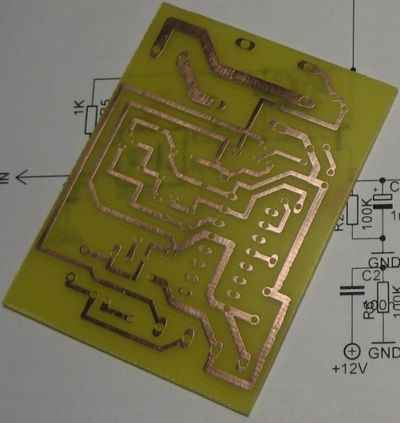
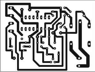
PCB
Download PCB and Schematic Eagle files
 |
 |
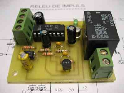
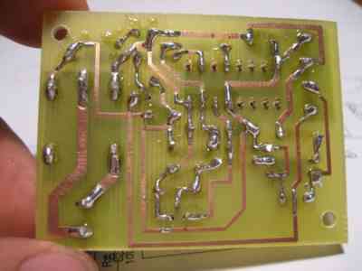
Photos
 |
|
Video
