Dylan McGrath
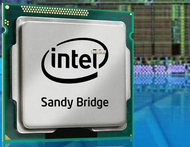
Intel Corp. disclosed more technical details of its 32-nm Sandy Bridge processor at the International Solid-State Circuits Conference here Tuesday (Feb. 22), including further description of its modular ring interconnect, design techniques used to minimize the cache's operational voltage and the inclusion of debug bus for monitoring traffic on the interconnect.
The 32-nm Sandy Bridge processor integrates up to four x86 cores, a power/performance optimized graphic processing unit (GPU) and DDR3 memory and PCI Express controllers on the same die, according to the paper presented at ISSCC Tuesday by Ernest Knoll, a designer at Intel's design center in Haifa, Israel. Sandy Bridge features 1.16 billion transistors and a die size of 216 square millimeters.

The Sandy Bridge IA core implements several improvements that boost performance without increasing power consumption, including an improved branch prediction algorithm, a micro-operation cache and a floating point advanced vector extension, according to the paper. Also, the devices' CPUs and GPU share the same 8MB level-3 cache memory.
Intel provided the first details about the Sandy Bridge family of heterogeneous processors at the Intel Developer Forum here last September. Intel introduced the first Sandy Bridge products, the second generation of the company's Core processor family, at the Consumer Electronics Show in January. Some of the devices have been shipping since early January and Intel expects them to be incorporated into more than 500 laptop and desktop PC designs this year.
Minimize power consumption
Because Sandy Bridges' x86 cores and L3 cache share the same power plane, Intel faced the challenge that the minimum voltage needed to keep the L3 cache data may have limited the minimum operating voltage of the cores, increasing the power consumption of the system, according to the paper. Intel got around this issue by developing several circuit and logic design techniques to minimize the minimum operational voltage of the L3 cache and the register files of the chip to bring it to a lower level than the core logic.
One of the techniques used to skirt the issue was a shared p-channel MOSFET technique that weakens the memory cell pull up device effective strength that solves the problem of RF write-ability degradation at low voltages that can be created by manufacturing process variations.
Thanks to the use of these design techniques, Sandy Bridge's power dissipation ranges from 95W for a four-core device operating in a high-end desktop to17W for a two-core Sandy Bridge running an optimized mobile product.
Sandy Bridge also introduces a debug bus that allows monitoring the traffic between the x86 cores, GPU, caches and system agent on the processor internal ring, according to the paper. The bus, dubbed the Generic Debug eXternal Connection (GDXC), allows chip, system or software debuggers to sample ring data traffic as well as ring protocol control signals and drive it to an external logic analyzer, where it can be recovered and analyzed.
Sandy Bridge also includes two different types of thermal sensors to monitor the temperature of the die, according to the paper. One is a diode-based thermal sensor on each core that compares the diode voltage to output the temperature, providing information for throttling, catastrophic function and fan regulation. The second is a much smaller CMOS-based thermal sensor with a more limited temperature range that can be placed at several locations inside the core to provide an accurate picture of core hot spots.
Earlier this year, Intel discovered a design flaw in one of the support chips for the first quad-core version of Sandy Bridge that began shipping Jan. 9. The company came up with a quick fix for the issue and temporarily halted shipments of the support chip. Intel later resumed shipments of the flawed chip to PC suppliers that were implementing it in systems were the flaw would not be an issue.
