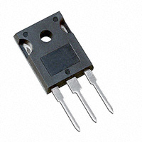
Datasheet Infineon IRFP3703PBF
| Manufacturer | Infineon |
| Series | IRFP3703 |
| Part Number | IRFP3703PBF |

30 V Single N-Channel HEXFET Power MOSFET in a TO-247AC package
Datasheets
SMPS MOSFET PD -95481 IRFP3703PbF
HEXFET® Power MOSFET
Applications l Synchronous Rectification l Active ORing l Lead-Free Benefits l Ultra Low On-Resistance l Low Gate Impedance to Reduce Switching Losses l Fully Avalanche Rated TO-247AC Absolute Maximum Ratings
Parameter
ID @ TC = 25°C ID @ TC = 100°C IDM PD @TC = 25°C PD @TA = 25°C VGS dv/dt TJ, TSTG Continuous Drain Current, VGS @ 10V Continuous Drain Current, VGS @ 10V Pulsed Drain Current Power Dissipation Power Dissipation Linear Derating Factor Gate-to-Source Voltage Peak Diode Recovery dv/dt Junction and Storage Temperature Range VDSS
30V RDS(on) max
0.0028 ID
210A Max. 210 100 1000 230 3.8 1.5 ± 20 5.0 -55 to + 175 Units
A W W/°C V V/ns °C Thermal Resistance
Parameter
RJC RCS RJA Junction-to-Case Case-to-Sink, Flat, Greased Surface Junction-to-Ambient Typ.
0.24 Max.
0.65 40 Units
°C/W Typical SMPS Topologies
l l Forward and Bridge Converters with Synchronous Rectification for Telecom and Industrial Applications Offline High Power AC/DC Convertors using Synchronous Rectification 1
7/16/04 Notes through are on page 8 www.irf.com IRFP3703PbF
Static @ TJ = 25°C (unless otherwise specified)
Parameter Drain-to-Source Breakdown Voltage V(BR)DSS/TJ Breakdown Voltage Temp. Coefficient V(BR)DSS RDS(on) VGS(th) IDSS IGSS Min. 30 Static Drain-to-Source On-Resistance Gate Threshold Voltage 2.0 Drain-to-Source Leakage Current Gate-to-Source Forward Leakage Gate-to-Source Reverse Leakage Typ. 0.028 2.3 2.8 Max. Units Conditions V VGS = 0V, ID = 250µA V/°C Reference to 25°C, ID = 1mA 2.8 VGS = 10V, ID = 76A m 3.9 VGS = 7.0V, ID = 76A 4.0 V VDS = VGS, ID = 250µA 20 VDS = 24V, VGS = 0V µA 250 VDS = 24V, VGS = 0V, TJ = 150°C 200 VGS = 20V nA -200 VGS = -20V Dynamic @ TJ = 25°C (unless otherwise specified)
gfs Qg Qgs Qgd td(on) tr td(off) tf Ciss Coss Crss Coss Coss Coss eff. Parameter Forward Transconductance Total Gate Charge Gate-to-Source Charge Gate-to-Drain ("Miller") Charge Turn-On Delay Time Rise Time Turn-Off Delay Time Fall Time Input Capacitance Output Capacitance Reverse Transfer Capacitance Output Capacitance Output Capacitance Effective Output Capacitance Min. 150 Typ. 209 62 42 18 123 53 24 8250 3000 290 10360 3060 2590 Max. Units Conditions S VDS = 24V, ID = 76A ID = 76A nC VDS = 24V VGS = 10V, VDD = 15V, VGS = 10V ID = 76A ns RG = 1.8 VGS = 10V VGS = 0V VDS = 25V pF = 1.0MHz VGS = 0V, VDS = 1.0V, = 1.0MHz VGS = 0V, VDS = …
Prices
Model Line
- IRFP3703PBF
