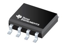
Datasheet Texas Instruments TPS54231DRG4
| Manufacturer | Texas Instruments |
| Series | TPS54231 |
| Part Number | TPS54231DRG4 |

3.5 to 28V Input, 2A, 570kHz Step-Down Converter with Eco-mode™ 8-SOIC -40 to 150
Datasheets
TPS54231 2-A, 28-V Input, Step-Down DC-DC Converter With Eco-modeв„ў datasheet
PDF, 1.3 Mb, Revision: D, File published: Oct 24, 2014
Extract from the document
Prices
Status
| Lifecycle Status | Active (Recommended for new designs) |
| Manufacture's Sample Availability | Yes |
Packaging
| Pin | 8 |
| Package Type | D |
| Industry STD Term | SOIC |
| JEDEC Code | R-PDSO-G |
| Package QTY | 2500 |
| Carrier | LARGE T&R |
| Device Marking | 54231 |
| Width (mm) | 3.91 |
| Length (mm) | 4.9 |
| Thickness (mm) | 1.58 |
| Pitch (mm) | 1.27 |
| Max Height (mm) | 1.75 |
| Mechanical Data | Download |
Parametrics
| Control Mode | Current Mode |
| Duty Cycle(Max) | 90 % |
| Iout(Max) | 2 A |
| Iq(Typ) | 0.075 mA |
| Operating Temperature Range | -40 to 150 C |
| Package Group | SOIC |
| Rating | Catalog |
| Regulated Outputs | 1 |
| Special Features | Enable,Light Load Efficiency,UVLO Adjustable |
| Switching Frequency(Max) | 570 kHz |
| Switching Frequency(Min) | 570 kHz |
| Type | Converter |
| Vin(Max) | 28 V |
| Vin(Min) | 3.5 V |
| Vout(Max) | 25 V |
| Vout(Min) | 0.8 V |
Eco Plan
| RoHS | Compliant |
Design Kits & Evaluation Modules
- Evaluation Modules & Boards: TPS54231EVM-372
TPS54231 28V Input, 3.3V Output, 2A Evaluation Module
Lifecycle Status: Active (Recommended for new designs)
Application Notes
- 800VA Pure Sine Wave Inverter's Reference Design (Rev. A)PDF, 3.1 Mb, Revision: A, File published: Aug 1, 2017
Thisapplicationnotedescribesthe designprinciplesand the circuitoperationof the 800VApureSineWaveInverter.The pureSineWaveinverterhas variousapplicationsbecauseof its key advantagessuchas operationwith verylow harmonicdistortionand cleanpowerlike utility-suppliedelectricity,reductionin audibleandelectricalnoisein fans,fluoresce - Designing Type III Compensation for Current Mode Step-Down Converters (Rev. A)PDF, 298 Kb, Revision: A, File published: Sep 15, 2010
One of the well-known benefits of current-mode control is that the system stability can be easily achieved by Type II compensation design. It is possible to improve the transient response of a current mode DC/DC converter by adopting Type III compensation to boost the crossover frequency and phase margin. Type III compensation is simple to design and needs only one extra component. - Create an Inverting Power Supply from a Step-Down Regulator (Rev. B)PDF, 472 Kb, Revision: B, File published: Oct 26, 2012
- Understanding Eco-mode(TM) OperationPDF, 249 Kb, File published: Dec 5, 2016
Model Line
Series: TPS54231 (4)
- TPS54231D TPS54231DG4 TPS54231DR TPS54231DRG4
Manufacturer's Classification
- Semiconductors > Power Management > Non-isolated DC/DC Switching Regulator > Step-Down (Buck) > Buck Converter (Integrated Switch)
