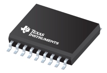
Datasheet Texas Instruments UC2526ADWTR
| Manufacturer | Texas Instruments |
| Series | UC2526A |
| Part Number | UC2526ADWTR |

Regulating Pulse Width Modulator 18-SOIC -25 to 85
Datasheets
Regulating Pulse Width Modulator datasheet
PDF, 597 Kb, File published: Sep 5, 1999
Extract from the document
Prices
Status
| Lifecycle Status | Active (Recommended for new designs) |
| Manufacture's Sample Availability | No |
Packaging
| Pin | 18 |
| Package Type | DW |
| Industry STD Term | SOIC |
| JEDEC Code | R-PDSO-G |
| Package QTY | 2000 |
| Carrier | LARGE T&R |
| Device Marking | UC2526ADW |
| Width (mm) | 7.5 |
| Length (mm) | 11.5 |
| Thickness (mm) | 2.35 |
| Pitch (mm) | 1.27 |
| Max Height (mm) | 2.65 |
| Mechanical Data | Download |
Parametrics
| Control Method | Voltage |
| Duty Cycle(Max) | 50 % |
| Frequency(Max) | 600 kHz |
| Frequency(Min) | 0.01 kHz |
| Gate Drive(Typ) | 0.2 A |
| Operating Temperature Range | -25 to 85 C |
| Package Group | SOIC |
| Rating | Catalog |
| Special Features | Error Amplifier,Multi-topology,Soft Start,Synchronization Pin |
| Topology | Boost,Buck,Flyback,Forward,Full-Bridge,Half-Bridge,Push-Pull |
| UVLO Thresholds On/Off | 7/6.8 V |
| Vin(Max) | 35 V |
| Vin(Min) | 8 V |
Eco Plan
| RoHS | Compliant |
Application Notes
- DN-62 Switching Power Supply Topology Voltage Mode vs. Current ModePDF, 66 Kb, File published: Sep 5, 1999
This design note explains the differences between voltage-mode and current-mode switching power supply topologies. It includes a circuit diagram for each mode and suggests criteria for choosing which mode to use.
Model Line
Series: UC2526A (7)
- UC2526ADW UC2526ADWG4 UC2526ADWTR UC2526AN UC2526ANG4 UC2526AQ UC2526AQG3
Manufacturer's Classification
- Semiconductors > Power Management > Offline and Isolated DC/DC Controllers and Converters > PWM and Resonant Controller
