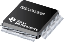
Fixed-Point Digital Signal Processor 179-BGA MICROSTAR
PDF, 134 Kb, Revision: A, File published: Jun 1, 2003
PDF, 164 Kb, Revision: A, File published: Sep 25, 2002
This application report demonstrates the procedure used to program the TMS320VC5509 digital signal processor (DSP) Real Time Clock (RTC). Basic operations of the RTC, such as reading and writing the time, as well as interrupt configuration, are covered. All interaction with the peripheral is accomplished using the Chip Support Library (CSL) RTC module. An example that illustrates usage of these ro
PDF, 80 Kb, Revision: A, File published: Feb 26, 2010
PDF, 75 Kb, Revision: A, File published: Dec 1, 2003
PDF, 458 Kb, Revision: A, File published: May 19, 2006
The enhanced host port interface (EHPI) on the TMS320VC5509 and TMS320VC5510 DSPs provides a 16-bit port through which a host device may access the internal and external memory space of the DSP. The flexibility of the EHPI interface allows various host devices to interface with the DSP using minimal or no external interface logic. This document describes various possible EHPI configurations and ex
PDF, 180 Kb, Revision: C, File published: Sep 10, 2004
This document provides a summary of the differences between the TMS320VC5509 and TMS320VC5509A. All efforts have been made to provide a comprehensive list of the differences between the two devices, this will be updated if additional changes are identified.As the focus of this document is the differences between the two devices, the descriptions of the behavior and functions of the devices ar
PDF, 140 Kb, Revision: A, File published: Jun 6, 2003
This document contains information and examples on accessing MMC/SD FLASH 7 cards through the C5509 MMC Controller operating in the native mode. The document provides an overview of the native mode functionality, including programming flow for the typical tasks that the user encounters when interfacing to the MMC cards in the native mode. For each operation, the procedures are highlighted with tab
PDF, 157 Kb, Revision: A, File published: Sep 26, 2008
This application report demonstrates the procedure used to program the TMS320VC5503/C5506/C5507/C5509/C5509A inter-integrated circuit (I2C) peripheral module. Basic operations of the I2C, including reading and writing, and the initialization of the I2C bus are covered. These operations are illustrated using the I2C routines provided in the chip support library (CSL). For more information, see the
PDF, 99 Kb, Revision: D, File published: Sep 9, 2008
This application report contains information and examples on how to disable the internal clock oscillator on the TMS320VC5503, TMS320VC5506, TMS320VC5507, TMS320VC5509, and TMS320VC5509A DSPs to minimize power consumption. The document contains an overview of how the internal clock oscillator operates, and how to disable it as part of the IDLE power-down feature. It also discusses how to wake up t
PDF, 304 Kb, Revision: C, File published: Oct 1, 2008
Bootloading the TMS320VC5506/C5507/C5509/C5509A digital signal processor (DSP) through the on-chip universal serial bus (USB) peripheral is part of the standard bootloader provided on the device. This document describes the procedures for physically connecting the DSP to a USB host, invoking the USB bootloader on the DSP, generating the correct boot table file, and downloading the boot table from
PDF, 222 Kb, Revision: F, File published: Sep 5, 2008
This document describes the features of the on-chip bootloder provided with the TMS320VC5503/C5506/C5507/C5509/C5509A digital signal processor (DSP). Included are descriptions of each of the available boot modes and any interfacing requirements associated with them as well as instructions on generating the boot table.

