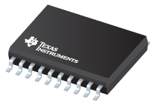
Datasheet Texas Instruments UCC28513DWRG4
| Manufacturer | Texas Instruments |
| Series | UCC28513 |
| Part Number | UCC28513DWRG4 |

Advanced PFC/PWM Combination Controllers 20-SOIC -40 to 105
Datasheets
Advanced PFC/PWM Combination Controllers datasheet
PDF, 1.5 Mb, Revision: C, File published: Sep 14, 2005
Extract from the document
Prices
Status
| Lifecycle Status | Active (Recommended for new designs) |
| Manufacture's Sample Availability | No |
Packaging
| Pin | 20 |
| Package Type | DW |
| Industry STD Term | SOIC |
| JEDEC Code | R-PDSO-G |
| Package QTY | 2000 |
| Carrier | LARGE T&R |
| Device Marking | UCC28513DW |
| Width (mm) | 7.5 |
| Length (mm) | 12.8 |
| Thickness (mm) | 2.35 |
| Pitch (mm) | 1.27 |
| Max Height (mm) | 2.65 |
| Mechanical Data | Download |
Parametrics
| Control Method | CCM |
| Device Type | PFC+PWM |
| Operating Supply Current | 4 mA |
| Operating Supply(Max) | 18 V |
| Operating Temperature Range | -40 to 105 C |
| Package Group | SOIC |
| Package Size: mm2:W x L | 20SOIC: 132 mm2: 10.3 x 12.8(SOIC) PKG |
| Peak Output Sink Current Gate Drive | 3 A |
| Peak Output Source Current Gate Drive | -2 A |
| Practical Operating Frequency(Max) | 0.5 MHz |
| Rating | Catalog |
| Special Features | Average Current Mode,Enable,OVP |
| Startup Current | 0.1 mA |
| UVLO Thresholds On/Off | 10.2/9.7 V |
Eco Plan
| RoHS | Compliant |
Design Kits & Evaluation Modules
- Evaluation Modules & Boards: UCC28521EVM
UCC28521 Evaluation Module
Lifecycle Status: Active (Recommended for new designs) - Evaluation Modules & Boards: UCC28514EVM
UCC28514 Evaluation Module
Lifecycle Status: Active (Recommended for new designs)
Application Notes
- UCC28517 100-W PFC power converter with 12-V, 8-W bias supply, Part 2PDF, 224 Kb, File published: Feb 28, 2005
To conclude the review of the UCC28517 PFC supply, this article covers the design of the second 12-V, 8-W power stage to be used as an auxiliary bias supply. - UCC28517 100-W PFC power converter with 12-V, 8-W bias supply, Part 1PDF, 202 Kb, File published: Feb 28, 2005
Power factor corrected (PFC) preregulators are generally used in ac/dc converters operating above 75 W or to meet line harmonic requirements. This article reviews the design of a 100-W ac/dc power stage with PFC. - Bootstrap Circuit for Green Mode ApplicationsPDF, 111 Kb, File published: Jan 27, 2006
- A New Synchronization Circuit for Power Converters (Rev. A)PDF, 209 Kb, Revision: A, File published: Apr 21, 2010
The synchronization of multiple PWM and PFC controllers is desirable for many reasons. The most common reason is that it keeps all the noise at one particular frequency and makes it easier to filter. The circuit described changes the slope of the ramp to lock the converter’s switching frequency to an applied signal by a phase locked loop turning it into a voltage controlled oscillator. Furthermore - Startup Current transient of the Leading Edge Triggered PFC ControllersPDF, 43 Kb, File published: Jun 30, 2004
- Avoiding Audible Noise at Light Loads When Using Leading Edge Triggered PFC Con (Rev. C)PDF, 57 Kb, Revision: C, File published: Apr 13, 2011
This application note applies to the TI average current mode, leading edge modulation PFC controllers. See Applicable Device Table for part numbers.
Model Line
Series: UCC28513 (5)
- UCC28513DW UCC28513DWG4 UCC28513DWR UCC28513DWRG4 UCC28513N
Manufacturer's Classification
- Semiconductors > Power Management > Offline and Isolated DC/DC Controllers and Converters > Power Factor Correction
