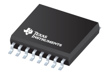
Datasheet Texas Instruments UC3854DW
| Manufacturer | Texas Instruments |
| Series | UC3854 |
| Part Number | UC3854DW |

High Power Factor Preregulator 16-SOIC 0 to 70
Datasheets
UCx854 High-Power Factor Preregulator datasheet
PDF, 949 Kb, Revision: A, File published: Dec 16, 2016
Extract from the document
Prices
Status
| Lifecycle Status | Active (Recommended for new designs) |
| Manufacture's Sample Availability | Yes |
Packaging
| Pin | 16 |
| Package Type | DW |
| Industry STD Term | SOIC |
| JEDEC Code | R-PDSO-G |
| Package QTY | 40 |
| Carrier | TUBE |
| Device Marking | UC3854DW |
| Width (mm) | 7.5 |
| Length (mm) | 10.3 |
| Thickness (mm) | 2.35 |
| Pitch (mm) | 1.27 |
| Max Height (mm) | 2.65 |
| Mechanical Data | Download |
Parametrics
| Control Method | CCM |
| Device Type | Single-phase PFC |
| Operating Supply Current | 10 mA |
| Operating Supply(Max) | 30 V |
| Operating Temperature Range | 0 to 70 C |
| Package Group | SOIC |
| Package Size: mm2:W x L | 16SOIC: 106 mm2: 10.3 x 10.3(SOIC) PKG |
| Peak Output Sink Current Gate Drive | 1 A |
| Peak Output Source Current Gate Drive | -1 A |
| Practical Operating Frequency(Max) | 0.2 MHz |
| Rating | Catalog |
| Special Features | Average Current Mode,Enable |
| Startup Current | 1.5 mA |
| UVLO Thresholds On/Off | 16/10 V |
Eco Plan
| RoHS | Compliant |
Application Notes
- U-134 UC3854 Controlled Power Factor Correction Circuit DesignPDF, 346 Kb, File published: Sep 5, 1999
The UC1854 provides active power factor correction for power systems that otherwise would draw non-sinusoidal current from sinusoidal power lines. This device implements all the control functions necessary to build a power supply capable of optimally using available power-line current while minimizing line-current distortion. This application note describes the concepts and design of a boost prere - DN-39E Optimizing Performance in UC3854 Power Factor Correction ApplicationsPDF, 277 Kb, File published: Sep 5, 1999
The performance of the UC3854 Power-Factor Correction IC in the 250W application example has been evaluated using a precision PFC/THD instrument. The result was a power factor of 0.999 and Total Harmonic Distortion (THD) of 3.81%, measured to the 50th line frequency harmonic at nominal line and full load. Users should get similar results at these conditions. as well as over most line and load rang - DN-41 Extend Current Transformer RangePDF, 37 Kb, File published: Sep 5, 1999
The problems with self reset of current transformers for unipolar pulse applications can be overcome with simple forced-reset techniques derived from magnetic amplifiers. Duty factors above 90% are achievable with these techniques. This design note describes a circuit configured for forced reset and a configuration that generates a negative voltage from the current transformer. - AC Requirements for Power Factor Correction CircuitsPDF, 29 Kb, File published: Mar 28, 2002
This technical brief identifies the recommended range of IAC for each of the devices within the UCC3854 family of PFC controllers. - Accurate PWM Duty Cycle ClampPDF, 58 Kb, File published: Jan 25, 2002
Power supply applications using current sense transformers require a duty cycle clamp on the pulse width modulator (PWM) to ensure transformer reset. Not all PWMs come with a duty cycle clamp presenting a problem for the power supply designer. This application note shows how to implement a duty cycle clamp by using a simple delay circuit.
Model Line
Series: UC3854 (9)
Manufacturer's Classification
- Semiconductors > Power Management > Offline and Isolated DC/DC Controllers and Converters > Power Factor Correction
