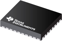
Datasheet Texas Instruments TPS544C25RVFR
| Manufacturer | Texas Instruments |
| Series | TPS544C25 |
| Part Number | TPS544C25RVFR |

4.5-V to 18-V, 30-A Voltage Mode PMBus™ SWIFT™ Step-Down DC-DC Converter with FSYNC 40-LQFN-CLIP -40 to 125
Datasheets
TPS544x25 4.5-V to 18-V, 20-A and 30-A SWIFT Synchronous Buck Converters with PMBus and Frequency Synchronization datasheet
PDF, 3.1 Mb, File published: May 15, 2015
Extract from the document
Prices
Status
| Lifecycle Status | Active (Recommended for new designs) |
| Manufacture's Sample Availability | No |
Packaging
| Pin | 40 |
| Package Type | RVF |
| Industry STD Term | LQFN-CLIP |
| JEDEC Code | R-PQFP-N |
| Package QTY | 2500 |
| Carrier | LARGE T&R |
| Device Marking | TPS544C25 |
| Width (mm) | 5 |
| Length (mm) | 7 |
| Thickness (mm) | 1.46 |
| Pitch (mm) | .5 |
| Max Height (mm) | 1.52 |
| Mechanical Data | Download |
Parametrics
| Control Mode | Voltage Mode |
| Duty Cycle(Max) | 80 % |
| Iout(Max) | 30 A |
| Iq(Typ) | 7.7 mA |
| Operating Temperature Range | -40 to 125 C |
| Package Group | LQFN-CLIP |
| Rating | Catalog |
| Regulated Outputs | 1 |
| Special Features | Adjustable Current Limit,Dynamic Voltage Scaling,Enable,Frequency Synchronization,PMBus,Power Good,Pre-Bias Start-Up,Remote Sense,Synchronous Rectification,Tracking,UVLO Adjustable,Voltage Margining |
| Switching Frequency(Max) | 1000 kHz |
| Switching Frequency(Min) | 200 kHz |
| Type | Converter |
| Vin(Max) | 18 V |
| Vin(Min) | 4.5 V |
| Vout(Max) | 5 V |
| Vout(Min) | 0.5 V |
Eco Plan
| RoHS | Compliant |
| Pb Free | Yes |
Design Kits & Evaluation Modules
- Evaluation Modules & Boards: TPS544C25EVM-681
TPS544C25EVM-681 Evaluation Module
Lifecycle Status: Active (Recommended for new designs)
Application Notes
- MOSFET power losses and how they affect power-supply efficiencyPDF, 162 Kb, File published: Jan 26, 2016
- Not All Jitter Is Created Equal (Rev. A)PDF, 555 Kb, Revision: A, File published: Jul 4, 2015
This application report offers a tutorial discussion on jitter in switching DC-DC converters. Not all power supply designs are equally susceptible to jitter, nor are they equally affected by jitter. Modes of switching jitter are defined and explained for several popular control architectures, which are then analyzed for sources of jitter. An example contrasting the amount of jitter and effect on o - SMT Guidelines for Stacked Inductor (Inductor On Top) on Voltage Regulator ICPDF, 409 Kb, File published: Feb 22, 2016
Model Line
Series: TPS544C25 (2)
- TPS544C25RVFR TPS544C25RVFT
Manufacturer's Classification
- Semiconductors > Power Management > Non-isolated DC/DC Switching Regulator > Step-Down (Buck) > Buck Converter (Integrated Switch)
