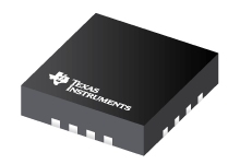
Datasheet Texas Instruments TPS54218RTET
| Manufacturer | Texas Instruments |
| Series | TPS54218 |
| Part Number | TPS54218RTET |

2.95V to 6V Input, 2A Synchronous Step-Down SWIFT™ Converter 16-WQFN -40 to 150
Datasheets
TPS54218 2.95-V to 6-V Input, 2-A Output, 2-MHz , Synchronous Step-Down Switcher With Integrated FETs (SWIFTв„ў) datasheet
PDF, 1.6 Mb, Revision: C, File published: Dec 26, 2014
Extract from the document
Prices
Status
| Lifecycle Status | Active (Recommended for new designs) |
| Manufacture's Sample Availability | No |
Packaging
| Pin | 16 |
| Package Type | RTE |
| Industry STD Term | WQFN |
| JEDEC Code | S-PQFP-N |
| Package QTY | 250 |
| Carrier | SMALL T&R |
| Device Marking | 54218 |
| Width (mm) | 3 |
| Length (mm) | 3 |
| Thickness (mm) | .75 |
| Pitch (mm) | .5 |
| Max Height (mm) | .8 |
| Mechanical Data | Download |
Parametrics
| Control Mode | Current Mode |
| Duty Cycle(Max) | 98 % |
| Iout(Max) | 2 A |
| Iq(Typ) | 0.35 mA |
| Operating Temperature Range | -40 to 150 C |
| Package Group | WQFN |
| Rating | Catalog |
| Regulated Outputs | 1 |
| Special Features | Enable,Frequency Synchronization,Power Good,Pre-Bias Start-Up,Synchronous Rectification,UVLO Adjustable |
| Switching Frequency(Max) | 2000 kHz |
| Switching Frequency(Min) | 200 kHz |
| Type | Converter |
| Vin(Max) | 6 V |
| Vin(Min) | 2.95 V |
| Vout(Max) | 4.5 V |
| Vout(Min) | 0.8 V |
Eco Plan
| RoHS | Compliant |
Design Kits & Evaluation Modules
- Evaluation Modules & Boards: TPS54218EVM-511
TPS54218 6V Input, 1.8V Output, 2A SWIFTВВ™ Converter Evaluation Module
Lifecycle Status: Active (Recommended for new designs)
Application Notes
- Calculating EfficiencyPDF, 175 Kb, File published: Feb 19, 2010
This application report provides a step-by-step procedure for calculating buck converter efficiency and power dissipation at operating points not provided by the data sheet. - Designing Type III Compensation for Current Mode Step-Down Converters (Rev. A)PDF, 298 Kb, Revision: A, File published: Sep 15, 2010
One of the well-known benefits of current-mode control is that the system stability can be easily achieved by Type II compensation design. It is possible to improve the transient response of a current mode DC/DC converter by adopting Type III compensation to boost the crossover frequency and phase margin. Type III compensation is simple to design and needs only one extra component. - Intel VR11.1 Server Reference DesignPDF, 38 Kb, File published: Jul 21, 2010
- Understanding Thermal Dissipation and Design of a HeatsinkPDF, 59 Kb, File published: May 4, 2011
Power dissipation performance must be well understood prior to integrating devices on a printed-circuit board (PCB) to ensure that any given device is operated within its defined temperature limits. When a device is running, it consumes electrical energy that is transformed into heat. Most of the heat is typically generated by switching devices like MOSFETs, ICs, etc. This application report discu - Semiconductor and IC Package Thermal Metrics (Rev. C)PDF, 201 Kb, Revision: C, File published: Apr 19, 2016
Model Line
Series: TPS54218 (2)
- TPS54218RTER TPS54218RTET
Manufacturer's Classification
- Semiconductors > Power Management > Non-isolated DC/DC Switching Regulator > Step-Down (Buck) > Buck Converter (Integrated Switch)
