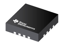
Datasheet Texas Instruments TPS54418RTER
| Manufacturer | Texas Instruments |
| Series | TPS54418 |
| Part Number | TPS54418RTER |

2.95V to 6V Input, 4A Synchronous Step-Down SWIFT™ Converter 16-WQFN -40 to 150
Datasheets
TPS54418 2.95-V to 6-V Input, 4-A Output, 2-MHz , Synchronous Step-Down Switcher With Integrated FETs (SWIFTв„ў) datasheet
PDF, 1.7 Mb, Revision: D, File published: Dec 26, 2014
Extract from the document
Prices
Status
| Lifecycle Status | Active (Recommended for new designs) |
| Manufacture's Sample Availability | Yes |
Packaging
| Pin | 16 |
| Package Type | RTE |
| Industry STD Term | WQFN |
| JEDEC Code | S-PQFP-N |
| Package QTY | 3000 |
| Carrier | LARGE T&R |
| Device Marking | 54418 |
| Width (mm) | 3 |
| Length (mm) | 3 |
| Thickness (mm) | .75 |
| Pitch (mm) | .5 |
| Max Height (mm) | .8 |
| Mechanical Data | Download |
Parametrics
| Control Mode | Current Mode |
| Duty Cycle(Max) | 98 % |
| Iout(Max) | 4 A |
| Iq(Typ) | 0.35 mA |
| Operating Temperature Range | -40 to 150 C |
| Package Group | WQFN |
| Rating | Catalog |
| Regulated Outputs | 1 |
| Special Features | Enable,Frequency Synchronization,Power Good,Pre-Bias Start-Up,Synchronous Rectification,UVLO Adjustable |
| Switching Frequency(Max) | 2000 kHz |
| Switching Frequency(Min) | 200 kHz |
| Type | Converter |
| Vin(Max) | 6 V |
| Vin(Min) | 2.95 V |
| Vout(Max) | 4.5 V |
| Vout(Min) | 0.8 V |
Eco Plan
| RoHS | Compliant |
Design Kits & Evaluation Modules
- Evaluation Modules & Boards: TPS54418EVM-375
TPS54418 3.3V Input, 1.8V Output, 4A SWIFTВ™ Evaluation Module
Lifecycle Status: Active (Recommended for new designs)
Application Notes
- Not All Jitter Is Created Equal (Rev. A)PDF, 555 Kb, Revision: A, File published: Jul 4, 2015
This application report offers a tutorial discussion on jitter in switching DC-DC converters. Not all power supply designs are equally susceptible to jitter, nor are they equally affected by jitter. Modes of switching jitter are defined and explained for several popular control architectures, which are then analyzed for sources of jitter. An example contrasting the amount of jitter and effect on o - Calculating EfficiencyPDF, 175 Kb, File published: Feb 19, 2010
This application report provides a step-by-step procedure for calculating buck converter efficiency and power dissipation at operating points not provided by the data sheet. - Designing Type III Compensation for Current Mode Step-Down Converters (Rev. A)PDF, 298 Kb, Revision: A, File published: Sep 15, 2010
One of the well-known benefits of current-mode control is that the system stability can be easily achieved by Type II compensation design. It is possible to improve the transient response of a current mode DC/DC converter by adopting Type III compensation to boost the crossover frequency and phase margin. Type III compensation is simple to design and needs only one extra component. - Intel VR11.1 Server Reference DesignPDF, 38 Kb, File published: Jul 21, 2010
- Understanding Thermal Dissipation and Design of a HeatsinkPDF, 59 Kb, File published: May 4, 2011
Power dissipation performance must be well understood prior to integrating devices on a printed-circuit board (PCB) to ensure that any given device is operated within its defined temperature limits. When a device is running, it consumes electrical energy that is transformed into heat. Most of the heat is typically generated by switching devices like MOSFETs, ICs, etc. This application report discu - Power Solution for the IntelВ® Atomв„ў E6X5CPDF, 27 Kb, File published: Jun 29, 2011
Power Solution for the IntelВ® Atomв„ў E6x5x - Semiconductor and IC Package Thermal Metrics (Rev. C)PDF, 201 Kb, Revision: C, File published: Apr 19, 2016
Model Line
Series: TPS54418 (3)
- HPA00835RTER TPS54418RTER TPS54418RTET
Manufacturer's Classification
- Semiconductors > Power Management > Non-isolated DC/DC Switching Regulator > Step-Down (Buck) > Buck Converter (Integrated Switch)
