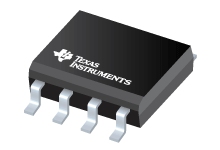
UC1705
UC2705, UC3705
www.ti.com SLUS370D – JULY 1995 – REVISED MARCH 2012 HIGH SPEED POWER DRIVER
Check for Samples: UC1705, UC2705, UC3705 FEATURES 1 1.5 A Source/Sink Drive
100 nsec Delay
40 nsec Rise Fall into 1000 pF
Inverting and Non-Inverting Inputs
Low Cross-Conduction Current Spike Low Quiescent Current
5 V to 40 V Operation
Thermal Shutdown Protection
Minidip and Power Packages DESCRIPTION
The UC1705 family of power drivers is made with a high sppeed Schottky process to interface between low-level
control functions and high-power switching devices -particularly power MOSFETs. These devices are also an
optimum choise for capacitive line drivers where up to 1.5 A may be switched in either direction. With both
inverting and non-inverting inputs available, logic signals of either polarity may be accepted, or one input can be
used to gate or strobe the other.
Supply voltages for both VS and VC can independently range from 5 V to 40 V. For additional application details,
see the UC1707/3707 data sheet (SLUS177).
The UC1705 is packaged in an 8-pin hermetically sealed CERDIP for -55В°C to 125В°C operation. The UC3705 is
specified for a temperature range of 0В°C to 70В°C and is available in either a plastic minidip or a 5-pin, power
TO-220 package. TRUTH TABLE (1) (2) (1)
(2) INV N.I OUT H H L L H H H L L L L L OUT = INV and N.I.
OUT = INV and N.i. BLOCK DIAGRAM 1 Please be aware that an important notice concerning availability, standard warranty, and use in critical applications of …

