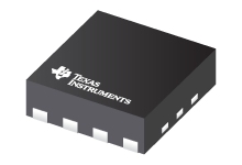
Datasheet Texas Instruments LDC0851
| Manufacturer | Texas Instruments |
| Series | LDC0851 |

Differentially Compensated and Highly Accurate Inductive Switch
Datasheets
LDC0851 Differential Inductive Switch datasheet
PDF, 2.5 Mb, Revision: A, File published: Jan 16, 2016
Extract from the document
Prices
Status
| LDC0851HDSGR | LDC0851HDSGT | |
|---|---|---|
| Lifecycle Status | Active (Recommended for new designs) | Active (Recommended for new designs) |
| Manufacture's Sample Availability | No | Yes |
Packaging
| LDC0851HDSGR | LDC0851HDSGT | |
|---|---|---|
| N | 1 | 2 |
| Pin | 8 | 8 |
| Package Type | DSG | DSG |
| Industry STD Term | WSON | WSON |
| JEDEC Code | S-PDSO-N | S-PDSO-N |
| Package QTY | 3000 | 250 |
| Carrier | LARGE T&R | SMALL T&R |
| Device Marking | 0851 | 0851 |
| Width (mm) | 2 | 2 |
| Length (mm) | 2 | 2 |
| Thickness (mm) | .75 | .75 |
| Pitch (mm) | .5 | .5 |
| Max Height (mm) | .8 | .8 |
| Mechanical Data | Download | Download |
Parametrics
| Parameters / Models | LDC0851HDSGR | LDC0851HDSGT |
|---|---|---|
| # Input Channels | 1 | 1 |
| Analog Supply (V), Min | 3.3 | 3.3 |
| Interface | Push/Pull | Push/Pull |
| Operating Temperature Range, C | -40 to 125 | -40 to 125 |
| Package Group | WSON | WSON |
| Package Size: mm2:W x L, PKG | See datasheet (WSON) | See datasheet (WSON) |
| Pin/Package | 8WSON | 8WSON |
| Rating | Catalog | Catalog |
| Sensor Frequency, Hz | 300KHz to 19MHz | 300KHz to 19MHz |
Eco Plan
| LDC0851HDSGR | LDC0851HDSGT | |
|---|---|---|
| RoHS | Compliant | Compliant |
Application Notes
- LDC0851 Quick-Start GuidePDF, 1.1 Mb, File published: Mar 16, 2016
- LDC0851 - TroubleshootingPDF, 991 Kb, File published: Jan 3, 2017
- Reliably Detect Faults In Circuit Breakers Using Contactless Inductive SwitchesPDF, 581 Kb, File published: Mar 20, 2017
Circuit breakers are commonly used to manage theflow of electricity within a home or office but theirreliable functionality is often taken for granted. Circuitbreakers rely on making a solid electrical contactbetween the AC mains and the rest of the circuitry withthe ability the open the circuit in the case of a shortcircuit or power surge. While this is a very robustmethod towards m - LDC1xxx LDC Target Design (Rev. A)PDF, 907 Kb, Revision: A, File published: May 9, 2017
Texas Instruments’ Inductive-to-Digital Converter (LDC) technology can accurately measure with a wide variety of target sizes, shapes, and material composition. There are several target design guidelines to maximize the effectiveness of an LDC measurement system. This application note covers the relevant factors of target design that affect inductive sensing, and provides guide - LDC Device Selection Guide (Rev. B)PDF, 360 Kb, Revision: B, File published: Mar 21, 2017
- EMI Considerations for Inductive SensingPDF, 151 Kb, File published: Feb 22, 2017
This application note explains various EMI reduction techniques to help improve EMI performance for TI'sInductance-to-Digital Converters (LDC). Each section details a general technique with references to otheruseful online documents. A list of relevant EMI reduction techniques is provided for specific devices withinthe LDC family of products. - Measuring Rp of an L-C Sensor for Inductive SensingPDF, 205 Kb, File published: Oct 1, 2015
When designing an application using TI’s LDC series of inductive sensors, it is necessary to know the L-C sensor’s equivalent parallel resistance RP at the sensor’s resonant frequency. The RP value changes as the target is moved; the minimum RP occurs when the metal target is closest to the sensor. The maximum RP occurs when the target is at the farthest distance. Accordingly, both values should b
Model Line
Series: LDC0851 (2)
Manufacturer's Classification
- Semiconductors> Sensing Products> Inductive Sensing> Inductive Switches
