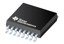
Datasheet Texas Instruments LDC2112
| Manufacturer | Texas Instruments |
| Series | LDC2112 |

2-Channel HMI Inductive Touch Buttons for Consumer and Low-Power Applications
Datasheets
LDC2112, LDC2114 Inductive Touch Solution for Low-Power HMI Button Applications datasheet
PDF, 1.8 Mb, Revision: B, File published: Apr 4, 2017
Extract from the document
Prices
Status
| LDC2112PWR | LDC2112PWT | LDC2112YFDR | LDC2112YFDT | |
|---|---|---|---|---|
| Lifecycle Status | Preview (Device has been announced but is not in production. Samples may or may not be available) | Preview (Device has been announced but is not in production. Samples may or may not be available) | Preview (Device has been announced but is not in production. Samples may or may not be available) | Preview (Device has been announced but is not in production. Samples may or may not be available) |
| Manufacture's Sample Availability | No | No | No | No |
Packaging
| LDC2112PWR | LDC2112PWT | LDC2112YFDR | LDC2112YFDT | |
|---|---|---|---|---|
| N | 1 | 2 | 3 | 4 |
| Pin | 16 | 16 | 16 | 16 |
| Package Type | PW | PW | YFD | YFD |
| Industry STD Term | TSSOP | TSSOP | DSBGA | DSBGA |
| JEDEC Code | R-PDSO-G | R-PDSO-G | S-XBGA-N | S-XBGA-N |
| Package QTY | 2000 | 250 | 3000 | 250 |
| Carrier | LARGE T&R | SMALL T&R | LARGE T&R | SMALL T&R |
| Width (mm) | 4.4 | 4.4 | 2.2 | 2.2 |
| Length (mm) | 5 | 5 | 2.2 | 2.2 |
| Thickness (mm) | 1 | 1 | .4 | .4 |
| Pitch (mm) | .65 | .65 | .4 | .4 |
| Max Height (mm) | 1.2 | 1.2 | .4 | .4 |
| Mechanical Data | Download | Download | Download | Download |
| Device Marking | 17M | 17M |
Parametrics
| Parameters / Models | LDC2112PWR | LDC2112PWT | LDC2112YFDR | LDC2112YFDT |
|---|---|---|---|---|
| # Input Channels | 2 | 2 | 2 | 2 |
| Active Supply Current(Typ), mA | 3.66 | 3.66 | 3.66 | 3.66 |
| Analog Supply (V), Min | 1.8 | 1.8 | 1.8 | 1.8 |
| Interface | GPIOs & I2C | GPIOs & I2C | GPIOs & I2C | GPIOs & I2C |
| L (Inductance) Resolution, Bits | 12 | 12 | 12 | 12 |
| Operating Temperature Range, C | -40 to 85 | -40 to 85 | -40 to 85 | -40 to 85 |
| Oscillation Amplitude(Max), V | 1.1 | 1.1 | 1.1 | 1.1 |
| Oscillation Amplitude(Min), V | 0.85 | 0.85 | 0.85 | 0.85 |
| Package Group | TSSOP | TSSOP | DSBGA | DSBGA |
| Package Size: mm2:W x L, PKG | 16TSSOP: 32 mm2: 6.4 x 5(TSSOP) | 16TSSOP: 32 mm2: 6.4 x 5(TSSOP) | See datasheet (DSBGA) | See datasheet (DSBGA) |
| Rating | Catalog | Catalog | Catalog | Catalog |
| Response Time(Max), 1/fsensor | N/A | N/A | N/A | N/A |
| Rp (Parallel Resonance Impedance) Resolution, Bits | N/A | N/A | N/A | N/A |
| Sensor Frequency, Hz | 1MHz to 30MHz | 1MHz to 30MHz | 1MHz to 30MHz | 1MHz to 30MHz |
| Sensor Rp Range(Max), Ohms | 10K | 10K | 10K | 10K |
| Sensor Rp Range(Min), Ohms | 35 | 35 | 35 | 35 |
| Stand-By Current(Typ), uA | 5 | 5 | 5 | 5 |
Eco Plan
| LDC2112PWR | LDC2112PWT | LDC2112YFDR | LDC2112YFDT | |
|---|---|---|---|---|
| RoHS | See ti.com | See ti.com | Compliant | Compliant |
Application Notes
- LDC2112/LDC2114 Inductive Touch System Design GuidePDF, 3.0 Mb, File published: Feb 2, 2017
The Inductive Touch System Design Guide presents an overview of the typical sensor mechanicalstructure and sensor electrical design for human machine interface (HMI) button applications. Themechanical design chapter discusses several factors that impact button sensitivity, including metalselection, sensor geometry, sensitivity dependence on target-to-coil distance, and mechanical isolation - Inductive Touch - Configuring LDC2114 Touch-Button SensitivityPDF, 771 Kb, File published: Mar 16, 2017
Erroneous or unintended button presses can result in a frustrating user experience in a human machine interface (HMI). Capacitive touch buttons trigger anytime a grounded object is brought close to the button; this can often cause false or erroneous button presses. One advantage mechanical buttons have over capacitive touch buttons is that a certain amount of force must be applied on the buttons f - EMI Considerations for Inductive SensingPDF, 151 Kb, File published: Feb 22, 2017
This application note explains various EMI reduction techniques to help improve EMI performance for TI'sInductance-to-Digital Converters (LDC). Each section details a general technique with references to otheruseful online documents. A list of relevant EMI reduction techniques is provided for specific devices withinthe LDC family of products.
Model Line
Series: LDC2112 (4)
Manufacturer's Classification
- Semiconductors> Sensing Products> Inductive Sensing> Inductance to Digital Converters
