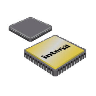
Hermetic Packages for Integrated Circuits
Ceramic Leadless Chip Carrier Packages (CLCC)
J44.A MIL-STD-1835 CQCC1-N44 (C-5)
44 PAD CERAMIC LEADLESS CHIP CARRIER PACKAGE 0.010 S E H S
D INCHES D3 j x 45o E3 B E h x 45o
0.010 S E F S
A A1
PLANE 2
PLANE 1 -E-MIN MAX MIN MAX NOTES A 0.064 0.120 1.63 3.05 6, 7 A1 0.054 0.088 1.37 2.24 -B 0.033 0.039 0.84 0.99 4 B1 0.022 0.028 0.56 0.71 2, 4 B2 B1 e
L -H-L3 0.072 REF -0.006 0.022 0.15 0.56 D 0.640 0.662 16.26 16.81 -D1 0.500 BSC 12.70 BSC -D2 0.250 BSC 6.35 BSC -D3 -0.662 E 0.640 0.662 16.26 16.81 2 16.81 -E1 0.500 BSC 12.70 BSC -E2 0.250 BSC 6.35 BSC -E3 -e 0.662 0.050 BSC
0.015 -16.81
1.27 BSC 0.38 2
-2 h 0.040 REF 1.02 REF 5 j 0.020 REF 0.51 REF 5 L 0.045 0.055 1.14 1.40 -L1 0.045 0.055 1.14 1.40 -L2 0.075 0.095 1.90 2.41 -L3 0.003 0.015 0.08 0.38 -ND 11 11 3 NE 11 11 3 N 44 44 -F-3
Rev. 0 5/18/94 B3 E1 E2 1.83 REF B3 e1 0.007 M E F S H S MILLIMETERS SYMBOL 1. Metallized castellations shall be connected to plane 1 terminals
and extend toward plane 2 across at least two layers of ceramic
or completely across all of the ceramic layers to make electrical
connection with the optional plane 2 terminals. L2
B2 L1
D2 e1
D1 NOTES: 2. Unless otherwise specified, a minimum clearance of 0.015 inch
(0.38mm) shall be maintained between all metallized features
(e.g., lid, castellations, terminals, thermal pads, etc.)
3. Symbol “N” is the maximum number of terminals. Symbols “ND” …

