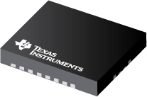
Datasheet Texas Instruments BQ24113RHLRG4
| Manufacturer | Texas Instruments |
| Series | BQ24113 |
| Part Number | BQ24113RHLRG4 |

Host-controlled Synchronous Switch-Mode Li-Ion Charger w/2A FET in QFN-20, 1- or 2-cell 20-VQFN -40 to 85
Datasheets
bq241xx Synchronous Switched-Mode, Li-Ion and Li-Polymer Charge-Management IC With Integrated Power FETs (bqSWITCHERв„ў) datasheet
PDF, 1.5 Mb, Revision: P, File published: Nov 30, 2015
Extract from the document
Prices
Status
| Lifecycle Status | Active (Recommended for new designs) |
| Manufacture's Sample Availability | Yes |
Packaging
| Pin | 20 |
| Package Type | RHL |
| Industry STD Term | VQFN |
| JEDEC Code | R-PQFP-N |
| Package QTY | 3000 |
| Carrier | LARGE T&R |
| Device Marking | CIJ |
| Width (mm) | 3.5 |
| Length (mm) | 4.5 |
| Thickness (mm) | .9 |
| Pitch (mm) | .5 |
| Max Height (mm) | 1 |
| Mechanical Data | Download |
Parametrics
| Absolute Vin (safety rating)(Max)( | 20 V |
| Battery Charge Voltage(Max) | 4.2,8.4 V |
| Battery Charge Voltage(Min) | 4.2,8.4 V |
| Cell Chemistry | Li-Ion/Li-Polymer |
| Charge Current(Max) | 2 A |
| Control Interface | Standalone (RC-Settable) |
| Control Topology | Switch-Mode Buck |
| Number of Series Cells | 1,2 |
| Operating Vin(Max) | 16 V |
| Operating Vin(Min) | 4.35 V |
| Package Group | VQFN |
| Package Size: mm2:W x L | 20VQFN: 16 mm2: 3.5 x 4.5(VQFN) PKG |
| Special Features | Integrated FET,Temp Monitoring (Thermistor Pin) |
| USB Feature | N/A |
Eco Plan
| RoHS | Compliant |
Design Kits & Evaluation Modules
- Evaluation Modules & Boards: BQ24113EVM
BQ24113 Evaluation Module
Lifecycle Status: Active (Recommended for new designs)
Application Notes
- bq24103/13/23/33 ComparisonPDF, 38 Kb, File published: Aug 12, 2011
This application report presents an overview of the differences among the bq24103, bq24113, bq24123 and bq24133. It assists design engineers in selecting the most suitable charger for their applications. - Power Dissipation Analysis & Circuit Design for Sync Switching Battery ChargerPDF, 402 Kb, File published: May 31, 2005
The bqSWITCHER(TM) (bq24100/03/05/08/13/15) is a highly integrated, switch-mode, Li-ion and Li-polymer battery charger IC. With two power MOSFETs, the gate drivers, and the controller fully integrated in the chip, the circuit design as well as the PCB layout has been appreciably simplified. However, it is still important to have a good understanding of the charger circuit design, layout principles - Implementations of Battery Charger and Power-Path Mgmt System Using bq241xxPDF, 752 Kb, File published: Jun 6, 2006
This application report presents four system topologies that can be used to fully implement a portable power management system solution using the bqSWITCHERв„ў. Test results and the advantages and issues of each topology are discussed. - Drive High Current LEDsPDF, 437 Kb, File published: Jan 25, 2007
This application report presents high-current LED driving requirements that use the TI integrated boost converter IC TPS6106x and integrated buck converter IC bqSWITCHERв„ў (bq2410x/11x/12x). Step-by-step design procedures, measurement results, and two dimming methods are provided and discussed.
Model Line
Series: BQ24113 (2)
- BQ24113RHLR BQ24113RHLRG4
Manufacturer's Classification
- Semiconductors > Power Management > Battery Management Products > Battery Charger IC
