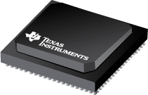
Datasheet Texas Instruments ADC12D500RF
| Manufacturer | Texas Instruments |
| Series | ADC12D500RF |

12-Bit, Dual 500-MSPS or Single 1.0-GSPS, RF Sampling Analog-to-Digital Converter (ADC)
Datasheets
ADC12D800/500RF 12-Bit, 1.6/1.0 GSPS RF Sampling ADC datasheet
PDF, 2.0 Mb, Revision: E, File published: Mar 25, 2013
Extract from the document
Prices
Status
| ADC12D500RFIUT | ADC12D500RFIUT/NOPB | |
|---|---|---|
| Lifecycle Status | Active (Recommended for new designs) | Active (Recommended for new designs) |
| Manufacture's Sample Availability | No | Yes |
Packaging
| ADC12D500RFIUT | ADC12D500RFIUT/NOPB | |
|---|---|---|
| N | 1 | 2 |
| Pin | 292 | 292 |
| Package Type | NXA | NXA |
| Industry STD Term | BGA | BGA |
| JEDEC Code | S-PBGA-N | S-PBGA-N |
| Package QTY | 40 | 40 |
| Carrier | JEDEC TRAY (10+1) | JEDEC TRAY (10+1) |
| Device Marking | ADC12D500RFIUT | ADC12D500RFIUT |
| Width (mm) | 27 | 27 |
| Length (mm) | 27 | 27 |
| Thickness (mm) | 2.38 | 2.38 |
| Pitch (mm) | 1.27 | 1.27 |
| Max Height (mm) | 2.4 | 2.4 |
| Mechanical Data | Download | Download |
Parametrics
| Parameters / Models | ADC12D500RFIUT | ADC12D500RFIUT/NOPB |
|---|---|---|
| # Input Channels | 2,1 | 2,1 |
| Analog Input BW, MHz | 2700 | 2700 |
| Architecture | Folding Interpolating | Folding Interpolating |
| DNL(Max), +/-LSB | 0.4 | 0.4 |
| DNL(Typ), +/-LSB | 0.4 | 0.4 |
| ENOB, Bits | 9.7 | 9.7 |
| INL(Max), +/-LSB | 2.5 | 2.5 |
| INL(Typ), +/-LSB | 2.5 | 2.5 |
| Input Buffer | Yes | Yes |
| Input Range, Vp-p | 0.8 | 0.8 |
| Interface | Parallel LVDS | Parallel LVDS |
| Operating Temperature Range, C | -40 to 85 | -40 to 85 |
| Package Group | BGA | BGA |
| Package Size: mm2:W x L, PKG | 292BGA: 729 mm2: 27 x 27(BGA) | 292BGA: 729 mm2: 27 x 27(BGA) |
| Power Consumption(Typ), mW | 2020 | 2020 |
| Rating | Catalog | Catalog |
| Reference Mode | Int | Int |
| Resolution, Bits | 12 | 12 |
| SFDR, dB | 74.3 | 74.3 |
| SINAD, dB | 60 | 60 |
| SNR, dB | 60.4 | 60.4 |
| Sample Rate(Max), MSPS | 500,1000 | 500,1000 |
Eco Plan
| ADC12D500RFIUT | ADC12D500RFIUT/NOPB | |
|---|---|---|
| RoHS | See ti.com | Compliant |
Application Notes
- Synchronizing the Giga-Sample ADCs Interfaced with Multiple FPGAsPDF, 943 Kb, File published: Aug 6, 2014
- AN-2177 Using the LMH6554 as a ADC Driver (Rev. A)PDF, 1.7 Mb, Revision: A, File published: Apr 26, 2013
This application report discusses the use of the Texas Instruments LMH6554 as an ADC driver. - From Sample Instant to Data Output: Understanding Latency in the GSPS ADCPDF, 392 Kb, File published: Dec 18, 2012
For many applications which use ultra high-speed ADCs, latency can be a critical performance specification. For example, if the ADC is used in any kind of feedback loop, then the absolute latency is an important factor. For a MIMO system such as a phased array radar, the relative difference and variability in latency becomes important. This application note covers latency in the GSPS ADC products, - AN-2132 Synchronizing Multiple GSPS ADCs in a System: The AutoSync Feature (Rev. G)PDF, 169 Kb, Revision: G, File published: Feb 3, 2017
- Maximizing SFDR Performance in the GSPS ADC: Spur Sources and Methods of MitigatPDF, 720 Kb, File published: Dec 9, 2013
The SFDR performance of an ADC is limited by the largest spur in the spectrum from DC to Fs / 2. These spurs can either be reduced or avoided entirely for maximum SFDR performance, based on the application. This reference design explores the reason behind spurs in the 10-bit and 12-bit GSPS ADCfamily. The specific products covered are: ADC12D1800RF, ADC12D1600RF, ADC12D1000RF, ADC12D800RF, ADC12
Model Line
Series: ADC12D500RF (2)
Manufacturer's Classification
- Semiconductors> Data Converters> Analog-to-Digital Converters (ADCs)> High Speed ADCs (>10MSPS)
