This experiment shows how to turn LEDs into light sensors. Since the Blinkenlight Shield has 20 of them this turns the Blinkenlight Shield into a 20 pixel „camera“.
Schematics
Before I explain why the schematics got their current form let’s just have a short look at them:
Please notice that the choice of the resistors is not arbitrary. The values meet some design criteria.
- The per LEDs must be limited as to not overdrive the LEDs.
- The current to the LEDs must be limited as to not overload the Arduino.
- The current to the LEDs shall be as high as possible in order to get good brightness.
- The load on the serial pins must not interfere with serial communication in order to avoid interference with the boot loader.
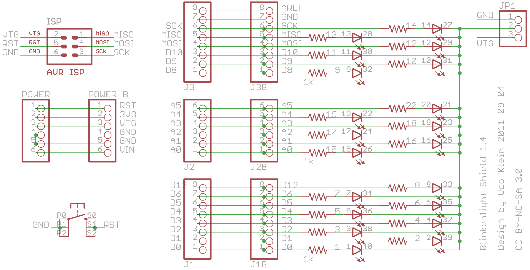
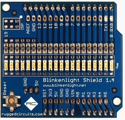
My experiments indicated that 1k resistors fit these requirements at least for the 4 Arduino boards I have around. For the unlikely case that some Arduinos will have issues with this setup I added a jumper in order to disconnect the LEDs from ground. You may notice that this jumper also allows some rather unusual setup. It allows to connect the common cathode to +5V. There are two reasons for this. If you look at the board layout you will see that this layout allows to either place SMD leds or LED stripes. So if I wanted to place some LED stripe with a common anode then I would need this setup. The other reason is a surprise that I will not yet give away. I will reveal it in the Blinkenlight experiments. For the time being it is only important to notice that by default the common cathode should be connected to the ground pin.
Before we proceed change the jumper setup to connect the common cathode to 5V. It will not harm the LEDs. If you notice that the lights have gone out, great. That’s how it is supposed to happen. Just don’t forget to reset the jumper to the default setup after this experiment.
The initial observation is that LEDs act like photodiodes. But LEDs are optimized to emit light – they make crappy light detectors. That is the photo current will be very small. In addition the number of A/D pins is usually limited whereas we have lots of digital pins. Since (CMOS) digital input pins have extraordinary high input impedance there is another way which we will explore now. The idea is to reverse bias the diodes by switching the IO pins to output low. Then the LEDs will not conduct and behave like capacitors. Once charged we will switch the IO pins to high Z and wait what happens. If there is light there will be a very small photo current. This current will discharge the LED-capacitors. The more light the more current the faster. After discharging the capacitor long enough we can detect that the pin floated from low to high. Measuring the time to reach this transition indicates how much light reached the LED.
The setup is a special case of the main loop. It sweeps over the pins and sets them to output 0V. Then it initializes the arrays to hold the reference milliseconds. After this the pins are set to input. Since they are already set to low this implies that the pullups will not be activated. We have now high Z input pins.
Notice that some pins are excluded. These pins are connected to the serial chip and the Arduino’s LED. They will not deliver any reasonable readings unless you have a board where these additional loads can be disconnected from the controller. In this case you may want to change the pin_is_ok function to return always true. All others must satisfy with a 17 pixel camera. Before you start to disconnect the serial connection don’t forget to think about how you want to transfer the data to your computer.
The main loop will now iterate the same thing over and over again. For each LED it will look if it has transitioned to high. If so it will pull it low by setting the pin to output. Then it computed the time since the last transition. Then it will put the pin into high Z mode again by setting it to input. Here I explicitly rely on the fact that pinMode commands are somewhat slow. Thus the LEDs will have quite some cycles for charging.
Once all LEDs are processed the results are pushed through the serial line. This must happen in a separate step in order to avoid jitter in the measurement timing.
You may wonder about the transform function. In theory and practice it can be ommited. I just introduced it to map the results into something that fits into 1 colum. Therefore I can use the serial monitor to visualize the output of this setup.
Demonstration Video
The video shows the “camera” in action. Unfortunately I did not notice that I had developed the sketch with the Arduino USB port to the right. So the output in the serial monitor is mirrored. Anyway the action is clearly visible.
Downloads
Source Code (Arduino) - download
Very Low-Cost Sensing and Communication Using Bidirectional LEDs - download