Mincior Vicentiu, Braila, Romania.
Inside the case of a regular wall charger with a 500mA transformer I’ve built a source in commutation for powering 10W LEDs by using a TOP242 integrated circuit in the primary part and the LM393 dual comparator on low voltage.
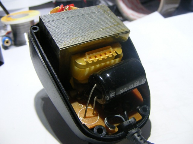 |
| Original 500mA transformer |
Here are the electrical schematic:
 Click for inlarge |
| Electronic schematic with the current limited TOP242 power source included |
And the printed circuit board schematic:
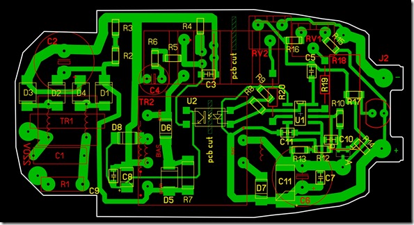 |
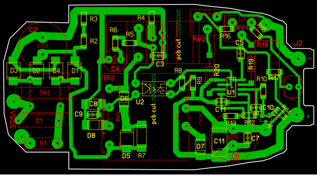 |
| Redesigned vinyl sticker PCB schematic for current limited TOP242 power source. First with SMD optocoupler and second with TH optocoupler |
Why work with TOP242 power source?
The TOP242 integrated circuit is an incredibly well built source in commutation. It has a limitation of power and temperature. It can be quite difficult to destroy. And when it goes out of its parameters it automatically blocks so than within only a few seconds it gets back to normal.
The functioning principle:
R1 resistor limits the charging current of capacitor C2 and creates a form of protection in the event that something happens with TOP242 circuit. Tr1 and C1 make a network filter with the purpose of minimizing the disturbances produced by the source in commutation. R2 and R3 discharge capacitor C2 when disconnecting the powering with 220V. At the pins of C2 we obtain, through the rectifier bridge Br1, a voltage of approximately 300V continuous current, which is applied to Tr2 transformer and to the TOP242Y circuit.
The group consisting of R7, D5 and D6 insures the lock of the currents induced by the inductance leakages from the windings of the transformer (without them, we would obtain high peaks of voltage which could damage the integrated circuit).
In this way, part of the kernel’s energy is recovered while the transistor from TOP242 integrated circuit is blocked. Resistor R4 limits the current peaks through the transistor of TOP242 circuit and through the primary winding of Tr2 transformer.
Diode D8 and capacitors C8 and C9 form a powering source for U2 optocoupler. D7, C6, C7 and C11 is the group that rectifies and filters the efective secondary voltage.
By using a dual comparator circuit LM393 I have conceived the two regulators: of current respectively of voltage.
The zener diode TL431 previously ordered is the reference source of the assembly and it insures a constant voltage of 2.5V by connecting the command input to the cathode.
Through the resistive divider R10, R12, R13 the reference is applied on the positive inputs of the regulators. And through Rv1 and Rv2 the values imposed by voltage and current are applied to the negative inputs of the comparators.
More technical details of TOP242 power source:
The LM393 circuit contains two comparators with open collector which means it requires a polarization resistance towards the positive terminal supply (R9).
If any of the outputs 1 or 7 of LM393 has the ground voltage then the voltage from the power source’s output is minimum (4V). Both comparators must be blocked so that the source to generate maximum voltage on the output.
All these being set, let’s see how does the voltage regulator works. We will begin by assuming that we have no voltage at the pins of C11 (Vout=0) and we ignore the current regulator because we haven’t connected any consumer on the output. On the input 2 we have the ground potential through R16 si Rv1 and the potential on the input 3 is the one of divided reference. Output 1 will be blocked, which will let the optocoupler free. The blocked optocoupler means allowing maximum voltage on the output. The voltage on C11 capacitor tends to grow on maximum.
Depending on Rv1′s position there will be a voltage threshold on C11 at which the positive voltage on input 2 will overcome the voltage on output 3. At this moment the regulator starts functioning and it will saturate the optocoupler that will shut down the source. Voltage at C11′s pins will drop down until input 3 is, again, more positive than input 2. In this way we obtain an oscillation with a frequency that depends on the reaction speed of the regulator as well as on the value of C5 capacitor called ripple. C5 stabilizes the assembly.
During all this time, since there is nothing connected at output, the difference of potential on R18 is zero, therefore on Rv2 as well, which will have the TL431′s anode potential. This means that input 6 is at ground, input 5 is more positive and the current regulator (output 7) is blocked. The output current has the permission to reach the highest peak. So let’s connect the load.
So, from Rv1 we obtain a constant output voltage – Vout. If we put a load at output (the 10W led) on R18 rezistor a voltage will drop. Part of that voltage will be applied through Rv2 and R20 on input 6. R18 rezistor is of low value, therefore the voltage drop on its pins will be of several hundreds of mV. That’s why R13 rezistor will be of only 1k (current reference – must be in the same range of values).
When the potential of input 6 exceeds the current reference from input 5, then the current regulator enters into functioning and it will saturate the optocoupler. This one will block the source so that the output voltage will drop to the point that it maintains the current from the led constant (translated through constant voltage drop on R18). The regulator enters once again into an oscillation, this time on current, the frequency of current ripple being determined by C5′s value, Rv2 slider’s position and R18′s value.
In this way we obtain the adjustment of the two parameters U and I, with the mention that we cannot maintain both the current and the voltage simultaneously constants. Initially we have the regimen of constant voltage (when the current can go up to the limit current) and then we have the regimen of constant current, when the output voltage drops from the limit value to whatever is necessary to maintain the current constant.
 |
|
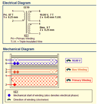
| Mechanical dimensions and electrical parameters of transformer | |
And now a few snapshots with the final assembly:
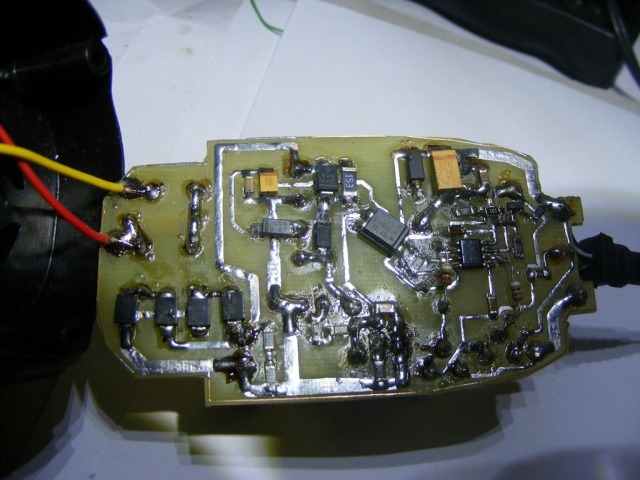 |
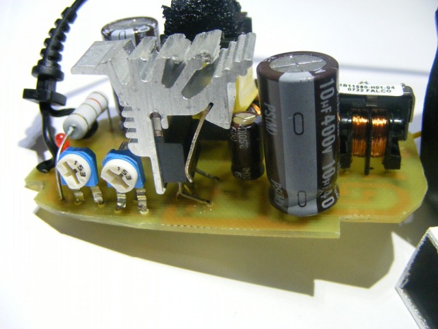 |
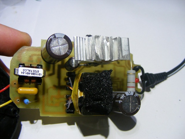 |
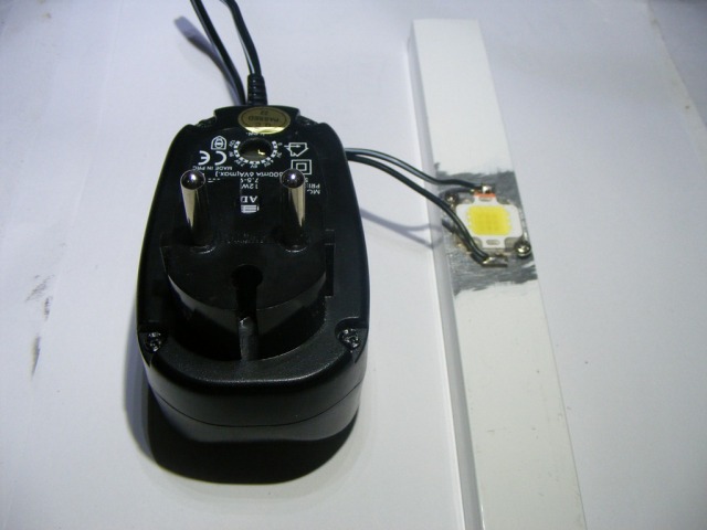 |
| Final PCB and assembly of power source |
Downloads
The project in Sprint Layout 6.0: Top242 constant current led power source - download.