The SCR is a switching semiconductor device, whose theoretical basics were published by Moll et al. in 1956. Although lower power parts have almost disappeared from the contemporary switching scene – being replaced by high-voltage BJTs, MOSFETs, and IGBTs – they still have no competition in the megawatt-switching area. 2 kA, 1.2 kV SCRs are used in locomotive drives, to control electrical furnaces in aluminum production plants, etc.
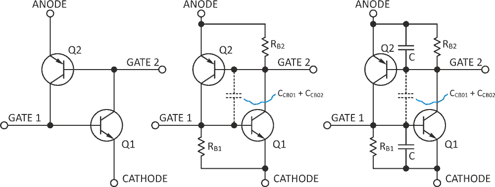
An SCR is a four-layer semiconductor device with a transistor equivalent shown in Figure 1a.
 |
|
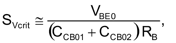
| Figure 1. | A basic SCR-like structure (a), gets well-defined values of gate and hold currents (b), and vastly improved immunity against undesired turn-on at steep rise of anode voltage (c). |
The device is in the off-state until a positive current pulse is fed into gate 1. After that, the four-layer structure between anode and cathode turns on, and the gate current is no longer needed. Here also, the base of Q2 can be used to turn on the SCR, but monolithic SCRs usually have cathode-referred gates only.
A more realistic transistor model contains base-emitter resistors for both PNP and NPN transistors, as in Figure 1b. Thus, an undesired turn-on by leakage currents of Q1 & Q2 is avoided, and the gate current has a defined value of:
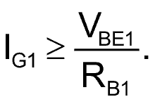
One limitation of SCRs in general is that if the risetime of anode voltage exceeds a critical rate, the SCR is turned on despite zero gate current. This anode voltage is called the commutation voltage, and it appears across switched inductive loads, when anode current goes to zero and drops below the hold level. The energy accumulated in the inductance tends to create an abrupt rise of anode voltage then. A commutation voltage also occurs when switching resistive loads by a combination of at least two SCRs, connected in a form of an analog multiplexer, where an SCR being turned on exerts an abrupt rise of anode voltage at another SCR.
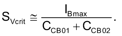
For the circuit of Figure 1b, the critical value of slope of commutation voltage is:
|
|
(1) |
Where VBE0 ~0.7 V, the typical voltage at which a silicon transistor is turned on. CCB01 and CCB02 are the collector-to-base capacitances of transistors Q1 & Q2. As the values of these capacitances decrease with rising emitter-to-collector voltage, the maximum values of these capacitances have to be used in Equation 1. For the transistors used in Figure 2, it can be estimated that CCB01 + CCB02 < 20 pF. For RB1 = RB2 = 6.8 kΩ, one gets SVcrit ≈ 5 V/µs – a value which is rather low, as monolithic SCRs usually achieve SVcrit ≈ 100 V/µs. Lowering the values of resistors RB1 and RB2 would help, but at the sacrifice of gate sensitivity (the circuit in Figure 1b can be made very sensitive, requiring a gate current of around 100 µA – one tenth the value typical for low power monolithic SCRs).
 |
|
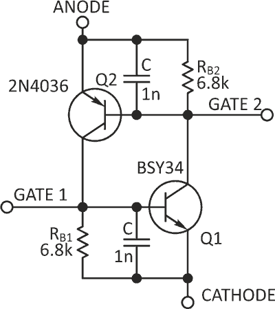
| Figure 2. | Adding two ceramic SMD capacitors C = 1 nF eliminates turn-on for ∆V up to 10 V. |
A way to retain low gate turn-on current, yet increase the critical steepness of commutation voltage, is in Figure 1c. By paralleling a capacitor C to the base-emitter junction of both NPN and PNP transistors, you get a theoretically infinite value of slope. The value of C is:
|
|
(2) |
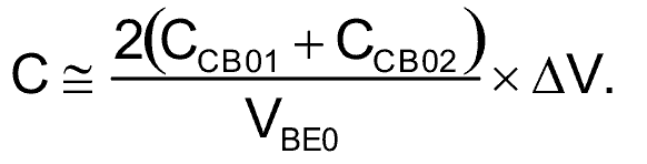
Here, for the sake of simplicity, the rise of anode voltage is assumed to linear, and ∆V is the magnitude of its rise. The practical limit follows then from the allowed maximum base current of the transistors used:
|
|
(3) |
If we assume IBmax = 200 mA, Equation 3 returns a realistic value of SVcrit ≈ 100 kV/µs.
Experimentally, the 2N4036 PNP transistor in Figure 2 has been used for its switching robustness; its maximum base current is 500 mA, while its maximum collector current is 1 A. An abrupt change of anode voltage (∆V = 9 V in 30 ns, or 300 V/µs) has been applied to the discrete SCR in Figure 2 without observing turn-on.
References
- J.L. Moll, M. Tanenbaum, J.M. Goldley and N. Holonyak, “p-n-p-n Transistor Switches”, Proc. IRE 44, 1174 (1956)